
Nobody looks up enough. That is the honest diagnosis of why so many buildings — otherwise well-designed, well-maintained, thoughtfully considered at every visible surface — carry a roof that was specified for cost and code compliance and nothing else. The roof is the building’s largest single surface, the element that defines its silhouette against the sky, and the first thing the eye resolves when a building is encountered from a distance. It is also the element that most homeowners accept as a fixed condition rather than a design decision — something inherited from the builder’s standard specification, tolerated through decades of occupation, and replaced only when it leaks.
That acceptance is expensive in ways that go beyond the aesthetic cost. A poorly designed or incorrectly specified roof underperforms thermally, accumulates water damage in details that were never properly resolved, and depresses the architectural quality of the building it covers regardless of what happens to the walls and windows below it. A roof that was chosen for cheapness forces the building to carry that decision visibly in every photograph, every street view, and every approach from the road. And a roof replacement — the moment when the existing covering fails and the building requires a new one — is the design opportunity that most homeowners waste by defaulting to the cheapest like-for-like replacement rather than asking whether the opportunity to redesign the roof entirely should be taken.
The roof’s design decisions extend far beyond the choice of covering material, though that choice is where most roof design conversations begin and end. The roof’s pitch — the angle at which its surfaces slope — determines the amount of internal volume available in the roof space, the rate at which rainwater leaves the surface, the range of materials that can technically be installed at that angle, and the building’s perceived proportion from the outside. The roof’s form — whether it is a simple gable, a hip, a mansard, a flat, a mono-pitch, or one of the more specific forms that particular building traditions developed for functional reasons that still apply — communicates the building’s architectural identity more directly than any other single design decision. The roof’s overhang, its eave detail, its ridge treatment, and the relationship between the roof plane and the wall below it are the architectural refinements that distinguish a building whose designer thought carefully about the roof from one whose designer accepted the contractor’s default.
The materials available for residential roofing now span a range wider than at any previous point in building history — from the ancient clay and slate traditions that have covered buildings for centuries, through the twentieth century’s asphalt and concrete additions, to the contemporary solar integration, green roof systems, and metal standing seam installations that bring the roof into direct conversation with the building’s energy performance as well as its aesthetic ambitions. Each material carries a specific set of performance characteristics, maintenance requirements, cost implications, and design associations that make it the right choice for one building type and the wrong choice for another. Understanding these relationships — between material, form, climate, building type, and design direction — is the knowledge that allows you to look at a roof and see not just what it is, but why it works or why it does not.
The fifty roof design ideas in this collection address that full range: from the fundamental choices about roof form and material that determine a building’s architectural character, through the specific design details that distinguish excellent roofing from adequate roofing, to the specialized roof types and applications that serve specific functional and aesthetic purposes. Whether you are replacing a failed roof covering and asking whether this is the moment to reconsider the material, extending a house and designing the roof of the new structure from scratch, or building new and making the roof design decision as the first architectural gesture that everything else will follow — these ideas are the reference point from which those decisions become more informed, more considered, and more likely to produce a building whose roof is as good as everything else you are building beneath it.
1. A Classic Gable Roof Design
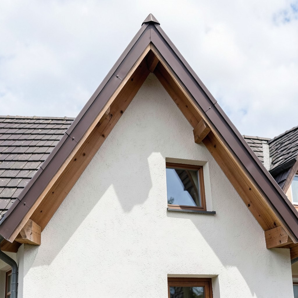
The gable roof is the roof form that most people picture when they think of a house — two sloping planes meeting at a central ridge, with the triangular gable wall at each end closing the roof volume — and its persistence across centuries of domestic architecture in every climate and every building tradition is not familiarity but function. The gable form sheds water effectively from both principal planes, provides a large internal volume under the ridge for attic space or habitable rooms, and meets the walls below it with the clean, simple geometry of a building that knows what it is. That clarity is not boring. It is the architectural confidence of a form that has been tested against every weather condition and found reliable.
The pitch of a gable roof is the design variable that most significantly changes both the building’s internal volume and its external character. A shallow pitch of fifteen to twenty degrees produces a low-profile gable that reads as a restrained, almost contemporary form — common in Scandinavian domestic architecture and in the prairie-influenced American residential tradition. A steep pitch of forty-five degrees or more produces the high, dramatic gable profile of Gothic-influenced domestic architecture, the Victorian terraced house, and the steeply pitched vernacular of Alpine building. The pitch decision is the one that must be made first and that determines every subsequent specification choice, because the covering material’s minimum pitch requirement must be met and the internal roof volume’s usability depends on whether the pitch provides the headroom that an occupied loft requires.
The gable end detail — the treatment of the triangular wall between the roof slopes and the building’s eave level — is the architectural refinement that most distinguishes a carefully designed gable roof from a generic one. A gable end finished flush with the wall below, with the roof covering returning to the gable apex and the verge tile or metal capping providing the weather seal at the roof edge, reads as tight and contained. A gable end with a projecting bargeboards — a timber fascia board running along the sloping roof edge that projects beyond the gable wall face — produces the shadow line and the material detail of a building that invested in its external finishing.
2. A Hip Roof Design
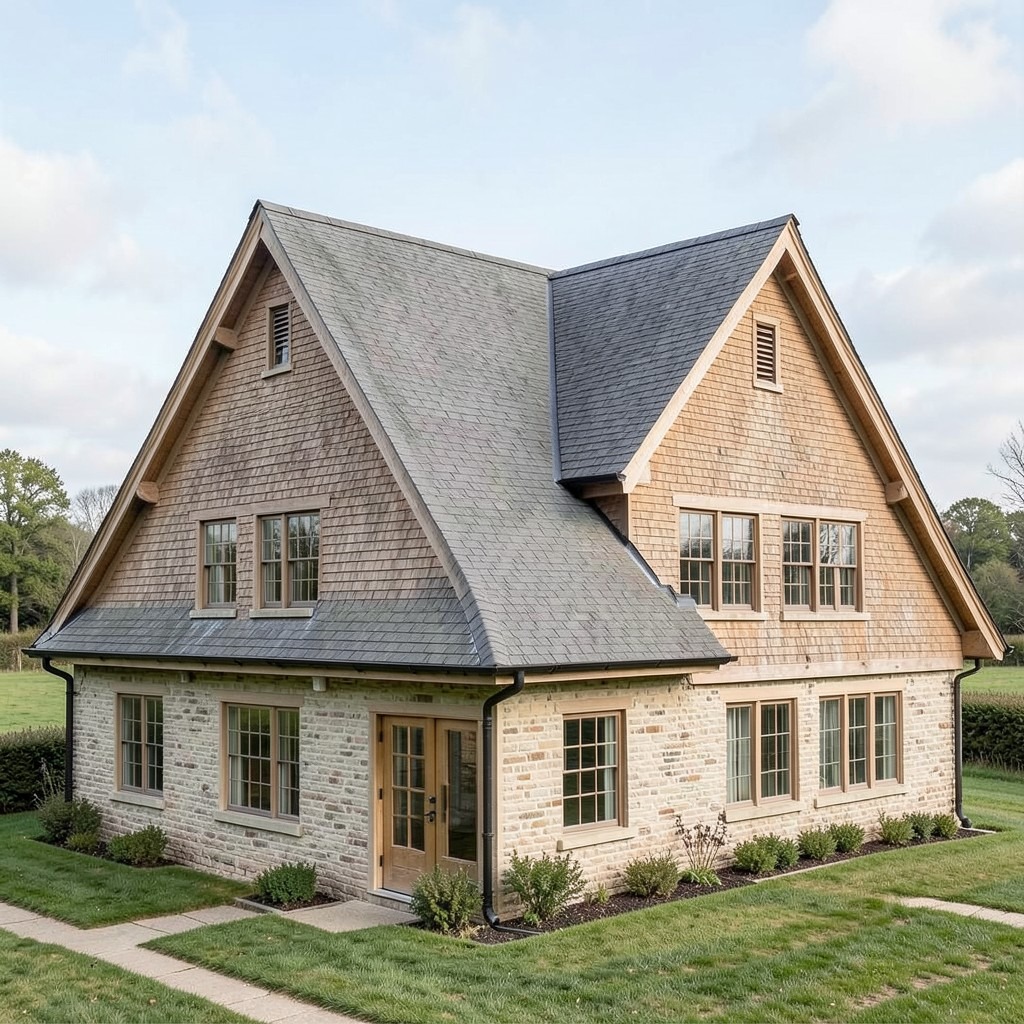
The hip roof — a roof form where all four sides of the building are covered by sloping planes that meet at a central ridge and at hip ridges at each end, with no vertical gable walls — produces a building profile with a specific quality of settled, low-profile solidity that the gable roof does not provide at comparable wall heights. The hip roof looks heavier on the building but performs better in exposed conditions: its four-sided slope presents no vertical gable wall to wind loading, and its geometry provides a more continuous and more reliable weather envelope than the gable form’s exposed triangular ends.
The structural complexity of a hip roof — the additional hip rafters that run from the ridge ends to the building’s corners, the hip-end planes that must be carefully detailed where they meet the main roof slopes, and the valley that forms where two hip planes intersect in a multi-hip building — makes the hip roof more expensive to construct and more technically demanding to detail correctly than the equivalent gable. The hip-end flashing and the valley lead work are the details where water ingress most commonly occurs in hip roofs that were built without adequate attention to the junction quality, and those details must be specified and installed to the standard that the geometry demands.
The proportional relationship between the hip roof’s pitch and the building plan dimensions determines whether the roof reads as a generous, inhabitable volume or as a low, tight covering that barely clears the walls below. A wide, square-plan building with a shallow hip roof produces the prairie-house quality of a horizontally emphatic building grounded firmly in its landscape. A narrow-plan building with a steep hip roof produces the cottage quality of a building whose roof occupies more of its visible profile than its walls — the specific domestic character of the English country house tradition that the hip roof form has served for centuries.
3. A Flat Roof Design for Modern Homes
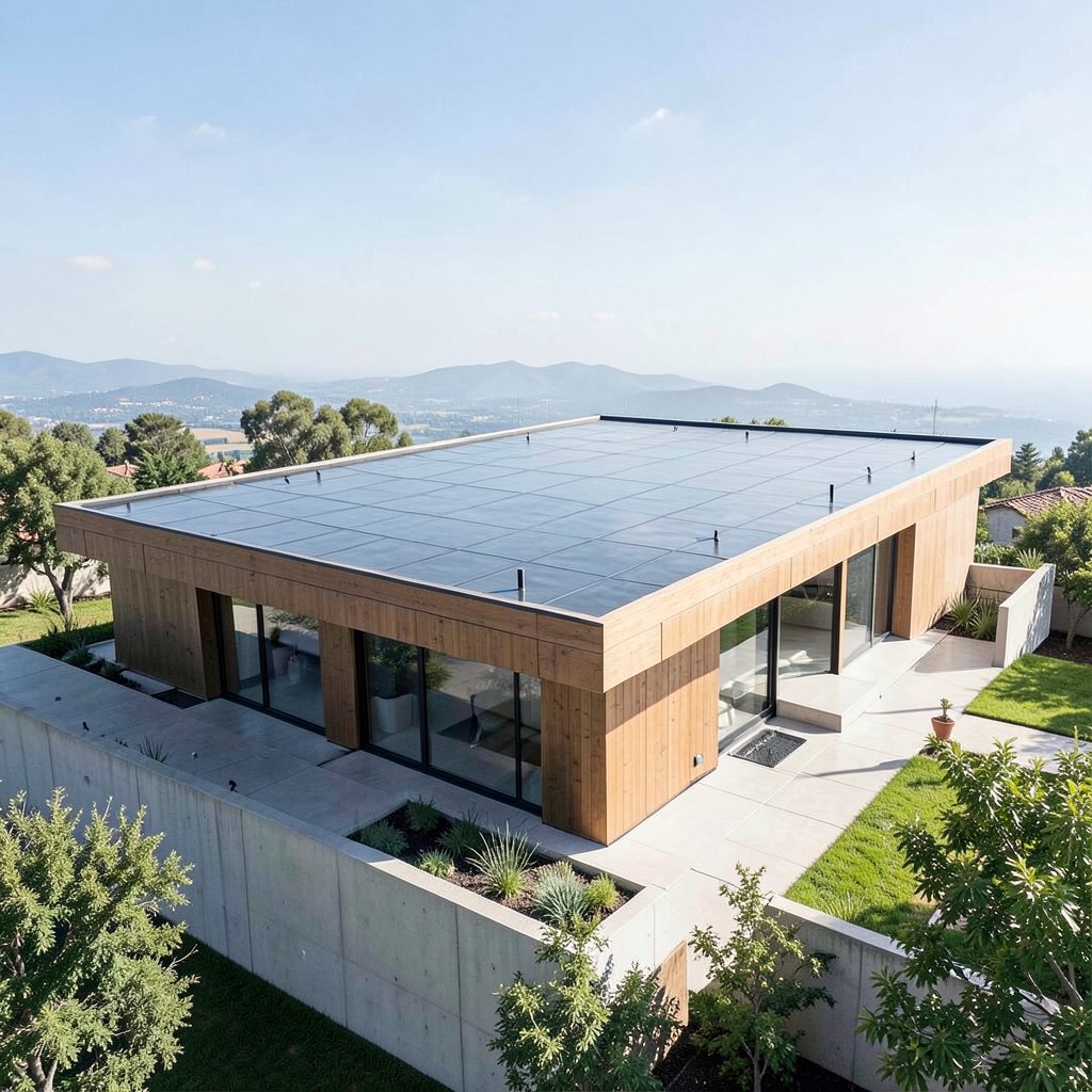
The flat roof is the design choice that the architectural mainstream and the popular imagination have argued about for a century, and the argument is not yet resolved because both sides are partially right. The flat roof is the natural companion of the modernist building — its horizontal plane extends the building’s geometry, it allows the roofline to remain low and the building’s proportions to emphasize width over height, and it provides the option of a usable roof terrace that pitched roofs cannot deliver without a major structural intervention. It also leaks more often than a pitched roof when specified incorrectly, and that failure history is the source of the flat roof’s reputation for unreliability.
The flat roof that performs reliably is not actually flat. The term is a misnomer that conceals the minimum fall — typically one-in-forty toward the drainage outlet — that the roof structure must provide to prevent ponding water from accumulating on the surface and stressing the waterproof membrane at the points where water sits longest. A genuinely level flat roof is a construction defect rather than a design specification, and the most common flat roof failure — standing water that degrades the membrane and eventually finds a pathway into the building — begins with inadequate fall provision at the design or construction stage.
The waterproof membrane selection for a flat roof is the specification decision with the most direct consequence for the roof’s long-term performance and maintenance requirement. A single-ply membrane — either EPDM rubber, TPO, or PVC — in a mechanically fastened or fully adhered installation provides a modern flat roof covering whose performance, when correctly specified and installed, exceeds the traditional felt systems that gave flat roofs their problematic reputation. The EPDM single-ply membrane, in particular, provides a covering whose flexibility accommodates the thermal movement of the roof deck through temperature cycling, whose resistance to UV degradation extends its service life beyond forty years in moderate climates, and whose joint bonding system eliminates the laps and seams that traditional felt systems were least reliable at.
4. A Mansard Roof Design
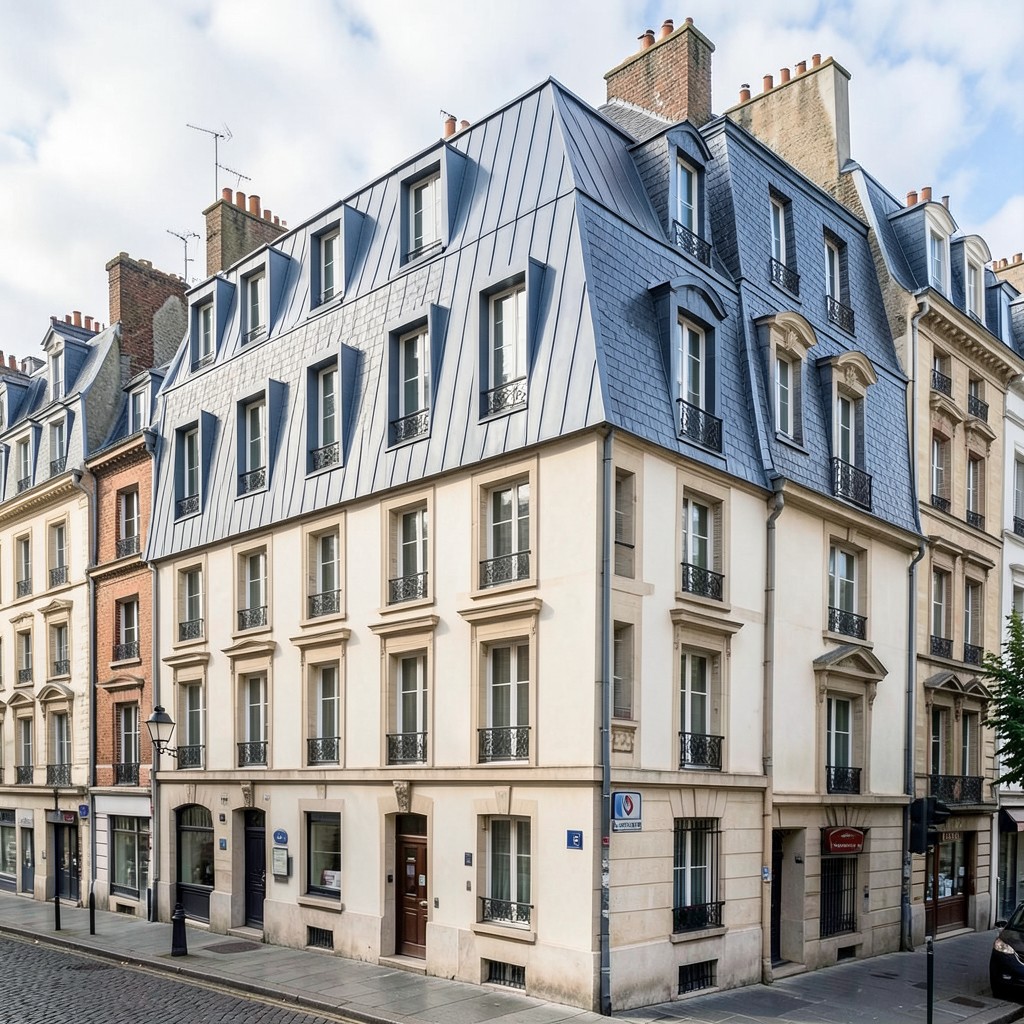
The mansard roof — the double-pitched roof form where each face of the building has a steep lower slope and a shallower upper slope separated by a change in pitch angle — was developed in seventeenth-century French architecture as the solution to a specific practical problem: the desire to maximize the habitable volume within the roof space while keeping the external wall height — and therefore the tax liability calculated on wall height in some historical French tax codes — as low as possible. The form solved its original problem so effectively that it spread from France across Europe and eventually to American domestic and commercial architecture, where it defined the character of a specific period of urban building whose influence persists in the mansard additions to existing buildings that remain one of the most common planning applications in urban residential areas.
The steep lower slope of the mansard roof — typically at sixty to eighty degrees from horizontal — is the surface that defines the building’s upper-floor character from the street and that contains the dormer windows that provide light and ventilation to the rooms within it. The steepness of this lower slope means that it reads almost as a vertical wall from the street-level viewing position, which makes the mansard a roof form that behaves as both a wall and a roof simultaneously — cladding the upper floors of the building in the roof covering material while simultaneously providing the structural enclosure of a conventional roof above.
The material selection for the mansard’s steep lower slope must address the close-up visibility that this near-vertical surface receives from street level, which is a very different visual condition from the distant, low-angle view from which most conventional roof materials are seen. Zinc standing seam cladding on a mansard lower slope reads as a contemporary urban material of genuine quality. Slate on the same surface provides the traditional quality of a building that references the historical mansard tradition with its original material. The material choice communicates the building’s architectural ambitions more directly from a mansard lower slope than from any conventional roof surface.
5. A Metal Standing Seam Roof
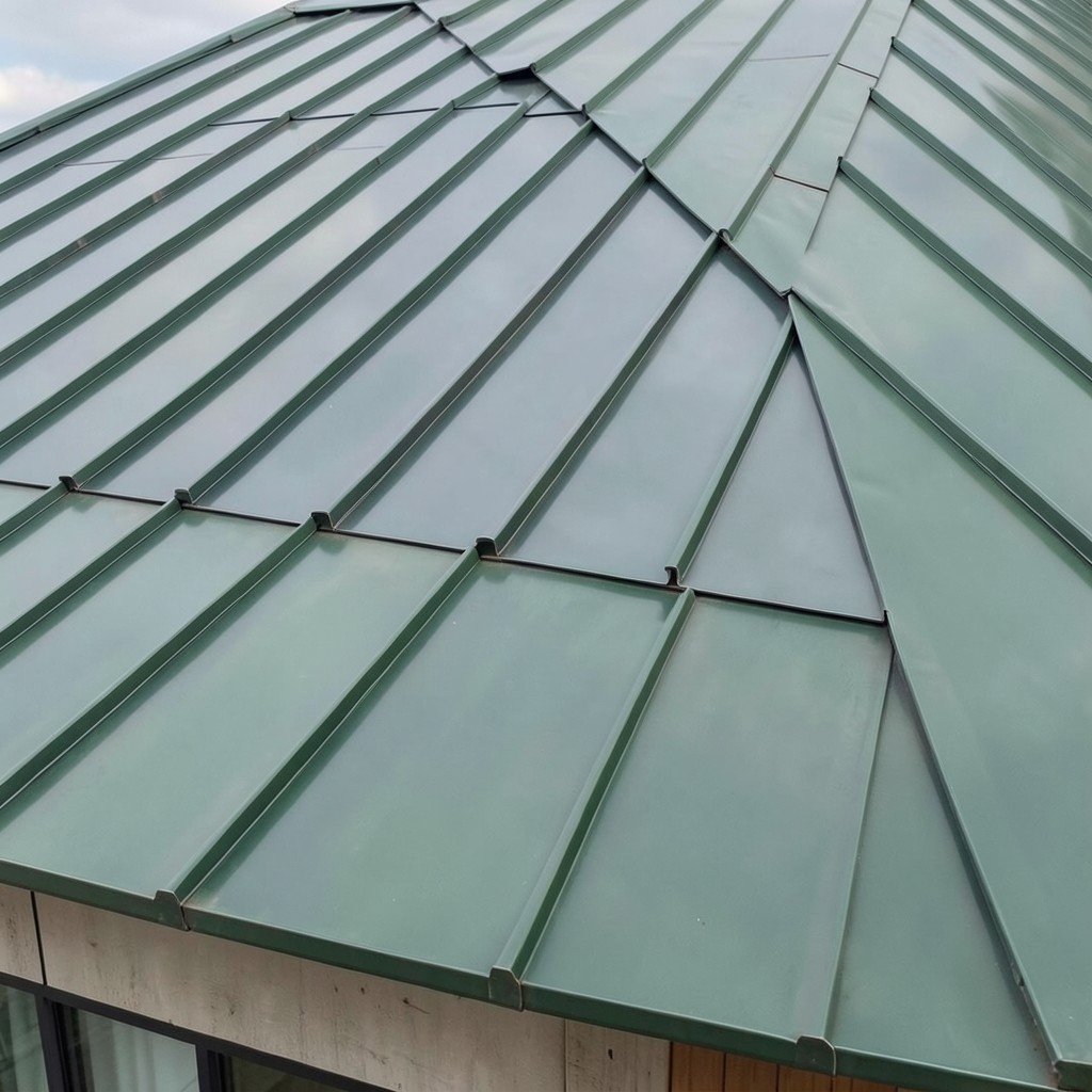
The standing seam metal roof — a roof covering formed from continuous metal panels whose edges are folded upward and locked together in a raised seam running parallel to the roof slope — is the roof specification that the contemporary architecture community has adopted as the standard for buildings that want a roof material combining longevity, low maintenance, design precision, and the specific material character of a roof that will outlast every other component of the building it covers. Done right, a standing seam roof is one of the most beautiful roofs available. Done cheaply, it is a maintenance liability whose panel joints fail within a decade.
The metal material for a standing seam roof — zinc, copper, aluminium, or steel — determines the roof’s long-term appearance, its maintenance requirement, and its cost per square meter at a range that spans from the affordable to the genuinely premium. Zinc develops the blue-grey patina that converts its initial bright metallic surface into the muted, mineral tone that weathers buildings into their landscape context with the specific elegance of a material that improves with age. Copper develops its green verdigris patina over decades, producing the roof color association of the great public buildings of the European tradition. Pre-weathered versions of both metals are available for installations where the building’s design requires the aged material appearance from the day of installation rather than after the years of weathering that the natural patina requires.
The panel width, the seam height, and the panel profile orientation — whether the seams run parallel to the slope or across it — are the detailing decisions that determine the standing seam roof’s visual character at the close range where its material quality is most apparent. A panel width of three hundred to four hundred millimeters produces the shadow line between seams that gives the standing seam roof its characteristic texture. A seam height of twenty-five to thirty millimeters provides the visual depth that makes the seam legible from a distance while providing adequate weather resistance at the joint.
6. A Green Roof Design
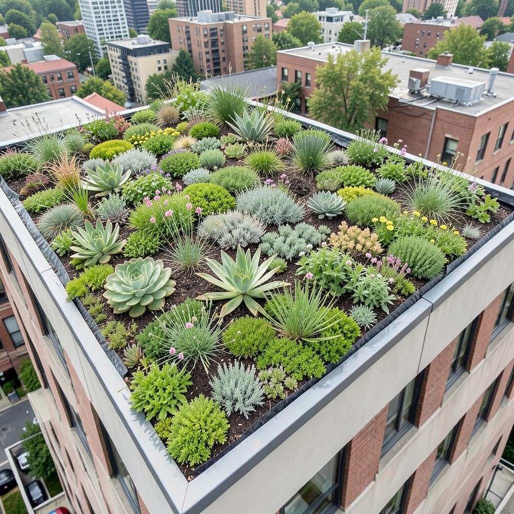
The green roof — a planted roof surface whose layers of waterproofing, root barrier, drainage, filter, growing medium, and planted layer convert a building’s largest single impermeable surface into a planted habitat — is the roof design choice that addresses the most questions about contemporary urban and suburban building simultaneously: the building’s thermal performance, its contribution to local biodiversity, its management of rainwater, its visual character from above, and its acoustic performance all improve when the hard roof surface is replaced with a planted one. The green roof is not a luxury addition. For buildings in dense urban areas where the ecological footprint of hard surfaces is a genuine planning and environmental concern, it is increasingly the responsible baseline.
The extensive green roof — a shallow-substrate system at fifty to one hundred and fifty millimeters growing medium depth, planted with sedums and other succulent ground-cover species — provides the standard domestic green roof specification at a weight loading of eighty to one-hundred-and-fifty kilograms per square meter in its saturated condition, which most domestic roof structures built to standard specifications can accommodate without additional structural support. The sedum varieties that cover an extensive green roof establish rapidly from pre-cultivated sedum mats or from plug plants, develop drought tolerance as their root systems reach the full growing medium depth, and provide the flowering succession from April through September that makes the roof ecologically productive as well as structurally sound.
The intensive green roof — a deeper substrate system of two hundred millimeters or more, capable of supporting perennial plants, shrubs, and in extreme specifications small trees — is the green roof type that most directly provides the quality of a designed garden at roof level. The structural loading of an intensive green roof — between three hundred and six hundred kilograms per square meter — requires specific structural design for the roof and its supporting structure, which restricts the intensive option to new-build projects where the structural specification can be set for the green roof’s requirements, or to existing buildings whose roof structure has been assessed and confirmed as adequate for the additional loading.
7. A Solar Roof Design
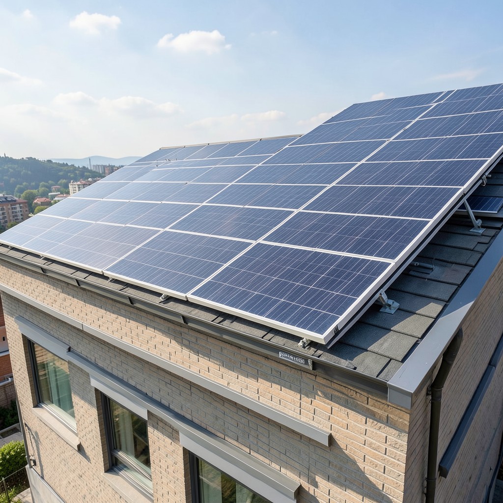
The solar roof — one where photovoltaic generation is integrated into the roof covering rather than applied to it as a retrofit addition — represents the specific design ambition of treating the roof as an active energy component of the building rather than as a passive weather enclosure that incidentally accepts solar panels bolted to its surface. The standard retrofit solar panel — a framed photovoltaic module fixed to a rail system above an existing roof covering — performs the energy generation function adequately but reads visually as something added to a roof that was not designed to receive it, and the aesthetic quality of the resulting installation reflects that disconnect at every viewing angle.
The solar tile — a photovoltaic roof tile that replaces the conventional clay or slate tile in the roof covering system and generates electricity from its upper surface while performing the weather-proofing function of a standard tile — provides the integrated aesthetic that the retrofit panel cannot achieve. Solar tile systems require the full roof replacement that provides their installation opportunity, and their installed cost per kilowatt of generating capacity exceeds that of the retrofit panel system. The payback period is longer. The visual result — a roof that reads as a designed, coherent surface rather than as a panelled energy installation — is the value proposition that justifies the premium for buildings where the roof’s aesthetic quality and the building’s architectural coherence are genuinely prioritised.
The orientation and pitch requirements for solar roof performance must inform the roof’s design from the beginning rather than being accommodated as a constraint after the fact. A south-facing roof slope at thirty to forty degrees from horizontal provides the optimal orientation for photovoltaic generation in northern hemisphere temperate climates, capturing the maximum annual solar irradiance across the full generating season. A building whose primary roof slope faces north — the condition that a constrained urban plot or a specific site context sometimes imposes — requires either a different roof form that provides south-facing generating surface or the acceptance that the solar generation potential is reduced by a factor that can be calculated and honestly assessed before the roof design is fixed.
8. A Slate Roof Design
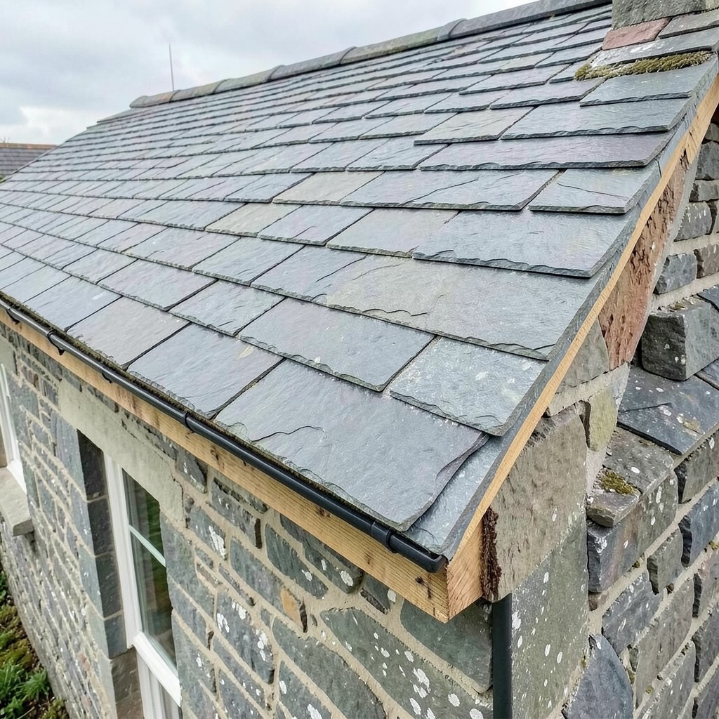
The slate roof is the covering material with the longest service life of any available roof option, and that fact alone makes it the correct specification for any building where a once-in-a-lifetime roof covering is the owner’s ambition. A natural slate roof of Welsh or Spanish origin, installed on a correctly prepared roof structure with correctly specified head lap and side lap dimensions, provides a service life of one hundred to one hundred and fifty years in the condition of the best maintained examples. The building beneath a natural slate roof will require more maintenance than the roof above it during the first century of the slate’s service life. That is the specific durability proposition that justifies the premium installation cost relative to every cheaper alternative.
The grade and source of natural slate determines the roof’s long-term performance more than the installation workmanship alone. Welsh slate — sourced from the quarries of North Wales whose geological formation produces the specific crystalline structure that gives the material its exceptional durability — is the reference standard against which other natural slate sources are measured. Spanish slate provides the most widely available and most cost-competitive natural slate specification in the current market, with a quality range from the excellent to the commercially marginal, and the specification must stipulate the grade and the quality standard explicitly rather than accepting a generic ‘natural slate’ description that covers a performance range the building owner cannot evaluate without specialist knowledge.
The installation of a natural slate roof requires the specific skills of a trained slater — a craftsperson whose ability to dress the slate to the required size and shape, to cut the holes for the fixing nails without cracking the tile body, and to lay the courses with the correct gauge and the correct side lap that prevents water penetration at the joints, cannot be substituted by a general roofing operative trained on concrete tile or asphalt shingle systems. The premium cost of skilled slating labor is the one cost reduction that the specification must resist, because poor installation of premium slate produces a roof that performs at the level of poor installation regardless of the material quality.
9. A Clay Tile Roof Design
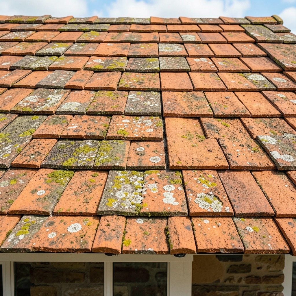
Clay roof tiles are the material that connects domestic architecture most directly to the earth beneath the building — fired from the same natural clay that the ground yields, shaped by the same manufacturing processes that have changed less over centuries than almost any other building material production method, and producing the warm red-orange-brown tonal range that reads as one of the most naturally belonging roof colors in the landscape. A clay tile roof ages into its setting in a way that concrete tile and asphalt shingle cannot replicate: the lichen and moss that colonize the clay surface over decades, the color variation between individual tiles that sun exposure and weathering differential produces, and the specific weight and depth of a clay tile course that no thinner, lighter material approaches.
The interlocking clay tile — the double-Roman, the pantile, and the various profile forms that different manufacturing traditions have developed for their specific regional roofing conventions — provides a faster installation rate than the plain tile because each tile covers a larger roof area and requires fewer fixing points per square meter of roof surface. The plain clay tile — a flat, single-lap tile in the English tradition, laid in staggered courses at a gauge determined by the head lap requirement — provides the most refined and most historically consistent clay tile appearance, with the close-set, texture-rich character of a tile roof that is composed of small elements rather than the larger, more visible profile of the interlocking alternatives.
The minimum pitch for clay tile installation depends on the tile profile and the climate’s typical wind-driven rain pressure: a plain clay tile requires a minimum pitch of thirty-five degrees for a weathertight installation in a standard temperate climate exposure, while the interlocking clay tile with its mechanical interlock at the side joints can be installed at pitches of seventeen to twenty degrees in sheltered conditions. Below these minima, the water-shedding mechanism of the tile — the direction of water off the tile surface by gravity and pitch angle — is insufficient to prevent wind-driven water from penetrating the head lap, and the roof’s performance becomes dependent on the underlay rather than on the tile surface.
10. A Thatch Roof Design
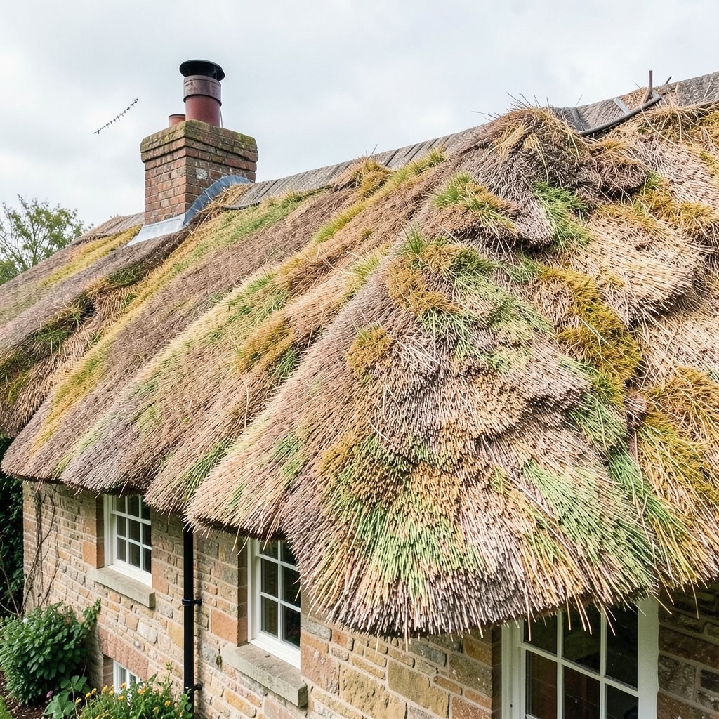
The thatched roof is the roof type whose cultural and material identity is more firmly established in the English rural imagination than any other building element, and it earns that status not through nostalgia but through a combination of material performance and aesthetic quality that no manufactured alternative has managed to approach at the specific domestic scale of the English vernacular cottage. The thatch is warm, acoustically absorptive, visually warm, and shaped by the hand of the thatcher who laid it — a skilled craftsperson whose understanding of the material’s behavior under weather and ageing produces a roof that reads as a made thing rather than an installed product.
The thatching material — long straw, combed wheat reed, or water reed — determines the roof’s texture, its thickness, its lifespan, and its regional appropriateness. Water reed — Phragmites australis, the Norfolk reed of the East Anglian fens tradition — provides the longest-lasting thatch specification at twenty-five to forty years before full re-thatching is required, and its regular, even cut end produces the precise, tight-finish surface associated with the most refined thatch installations. Long straw provides the more informal, flowing surface texture of the older agricultural tradition, with a shorter service life of fifteen to twenty-five years but a material character that suits the buildings of the arable farming counties where the tradition developed.
The fire risk associated with a thatched roof is the practical concern that most prospective owners of thatched properties wrestle with, and the insurance and management implications are real rather than theoretical. Modern thatching practice addresses the fire risk through the application of fire retardant treatments to the thatch surface, the installation of a fire-rated underlay board beneath the thatch layer where the roof structure provides the fixing substrate, and the installation of a spark arrestor at the chimney stack that prevents the airborne embers from chimney fires — the most common ignition source for thatched roof fires — from landing on the thatch surface.
11. A Butterfly Roof Design
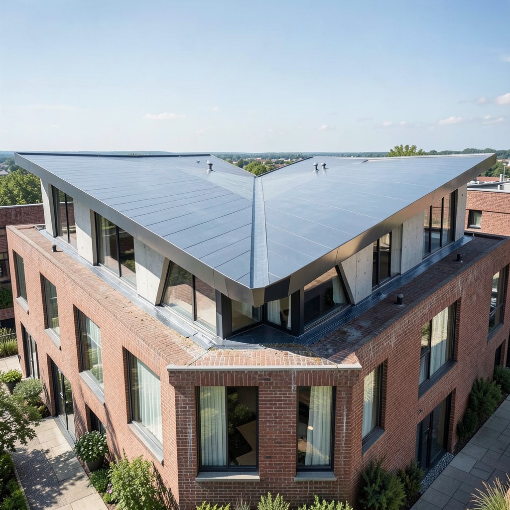
The butterfly roof — two roof planes sloping inward toward a central valley rather than outward from a central ridge, producing the V-form profile that gives the design its name — is the mid-century modernist roof type whose functional rationale and formal character are more disciplined than its unusual appearance suggests. The butterfly’s valley channel collects rainfall for directed discharge or retention. The raised wings at the building’s perimeter allow high-level windows in the wall sections below each raised edge, admitting the directional light quality that the clerestory window provides without the full structural addition of a monitor roof. These are not aesthetic gestures. They are the specific performance attributes that the butterfly form was developed to provide.
The valley drainage in a butterfly roof is the most critical and the most demanding detail in the entire building envelope. The central valley collects water from both roof planes and channels it to the drainage outlet at the valley’s lowest point, concentrating the full roof’s water discharge at a single location rather than distributing it across two guttered eaves. That concentration means the valley lining, the drainage outlet specification, and the overflow provision must be sized and installed for the full roof’s catchment area rather than for the half-roof catchment of a conventional eave gutter. The valley lining material — lead, zinc, or EPDM in a continuously welded system — must be specified for the high-water-volume condition of the valley’s function rather than for the lower exposure condition of a conventional eave detail.
The thermal performance of the butterfly roof requires specific insulation design at the valley detail, where the inverted geometry produces a cold bridge risk that the standard insulation layers applied to either roof slope cannot address without a valley-specific insulation strategy. The valley zone — where the two slopes meet and the structural elements concentrate — typically interrupts the continuous insulation layer that each individual slope carries, and the cold bridge at that junction produces the interior condensation risk that the building’s energy performance modelling must identify and the design must resolve before the roof is built.
12. A Shed or Mono-Pitch Roof Design
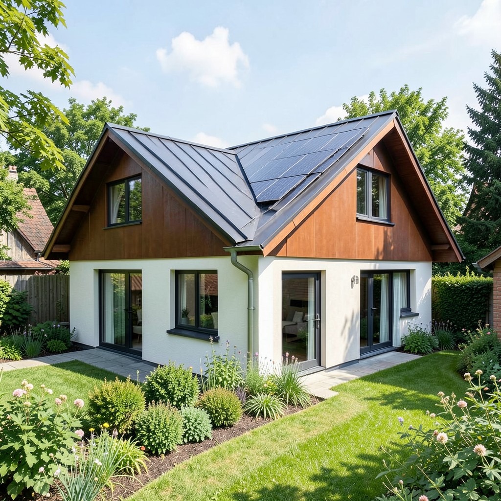
The mono-pitch roof — a single sloping plane covering the building from one high eave to one low eave, with no ridge — is the roof form that contemporary residential architecture has adopted most widely for extensions, ancillary buildings, and deliberately asymmetric new-build designs, and whose apparent simplicity conceals the design discipline its successful application demands. A mono-pitch that slopes in the right direction — toward the garden, away from the street, or in the specific orientation that the building’s massing and its solar performance require — reads as a considered architectural decision. The same form sloping in the wrong direction reads as a prefabricated shed.
The pitch range for a mono-pitch roof spans from the near-flat of a contemporary extension roof at three to five degrees through the moderate pitch of fifteen to twenty-five degrees that most metal and tile systems require to perform correctly, to the steep pitches of thirty degrees and above that some traditional single-slope vernacular buildings employ. The contemporary metal-clad mono-pitch at low pitch — a zinc or Corten steel single plane at five to ten degrees — is the architectural detail that reads as most deliberately designed when the material selection, the eave detail, and the building’s relationship to its context are all resolved with the same precision. The same roof in a budget corrugated steel reads as agricultural.
The thermal performance of a mono-pitch roof improves with the roof’s orientation because the single plane can be optimised for either solar gain avoidance in summer or solar panel generation in a way that a symmetrical pitched roof distributes between two opposing surfaces. A south-facing mono-pitch at the optimal solar collection angle provides the entire roof surface area as generating or passive solar collection surface — an efficiency that no other roof form provides when the building’s layout and the site’s orientation allow the mono-pitch to be positioned correctly.
13. A Gambrel Roof Design
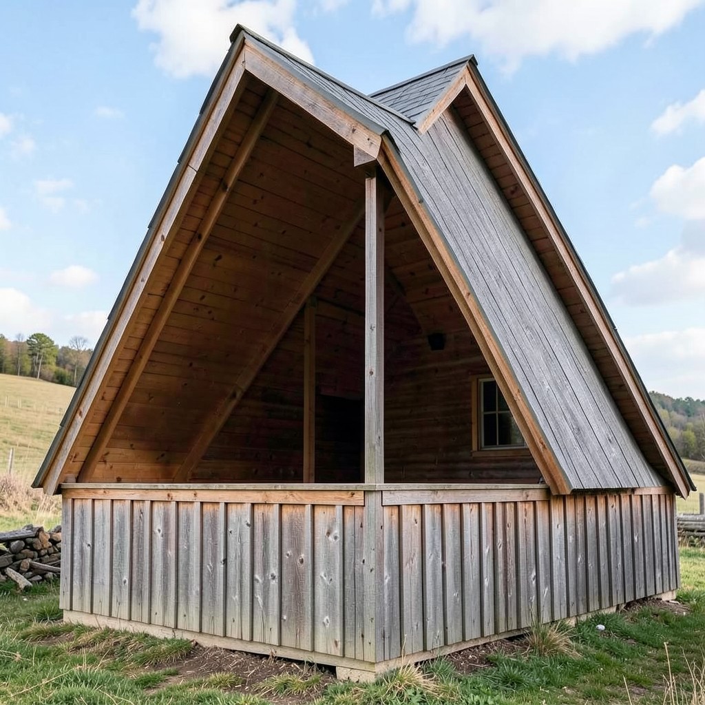
The gambrel roof — the two-sided roof form where each side has two slopes, a steep lower slope and a shallower upper slope, producing the barn-roof profile most associated with the American agricultural tradition — is the domestic architecture equivalent of an engineering optimization: more usable attic space per wall height than any other roof form, achieved through the geometric manipulation of the pitch relationship between the two slope segments on each side. The gambrel is not merely a decorative choice. It is a space efficiency calculation expressed in roof geometry.
The lower slope of a gambrel roof — typically at sixty to seventy degrees — provides the near-vertical wall surface that gives the roof space its maximum floor-adjacent headroom. The upper slope at thirty to forty degrees closes the roof volume above the lower slope’s top edge and provides the weather shedding performance that the steep lower slope alone cannot achieve efficiently. The break point between the two slopes — the point where the roof changes pitch — is the structural and visual hinge of the form, and its height above the eave line determines how much of the lower storey height is contained within the roof plane rather than in the wall below it.
The internal roof space of a gambrel roof — when the geometry is correctly proportioned for the building’s plan dimensions — provides a full additional floor of habitable space within the roof volume, with adequate headroom across the majority of the plan area rather than only at the central ridge. This space efficiency is the gambrel’s primary advantage over the standard gable at comparable wall heights, and it is the reason the form was adopted by the agricultural tradition for barns — buildings where maximum storage volume within a compact structural footprint was the design requirement.
14. A Sawtooth Roof Design
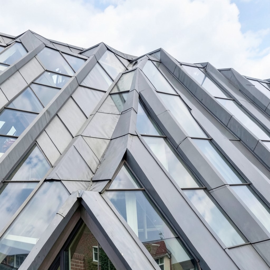
The sawtooth roof — a roof composed of multiple parallel ridges in a cross-sectional profile that resembles the teeth of a saw, each tooth formed by a steeply glazed north-facing surface and a shallower south-facing opaque surface — was developed in the industrial building tradition as the specific answer to the factory design problem of providing large-floor-area buildings with abundant, consistent, diffused daylight without the glare and solar heat gain that south-facing skylights produce. The north-facing glazed surface admits the consistent, diffused quality of northern sky light without direct solar penetration, and the multiple saw teeth distribute this light evenly across a large floor area in a way that perimeter windows cannot achieve for deep-plan buildings.
The contemporary residential and small commercial application of the sawtooth roof translates the industrial form’s light-harvesting logic into a domestic scale — a sawtooth section for a single-storey kitchen extension, a studio, or a workshop provides the specific quality of consistent, north-sky light that makes the interior genuinely functional for visual work without the solar heat gain management requirement that a south-facing glazed roof imposes. The floor area that a single sawtooth section illuminates effectively depends on the height of the glazed north-facing surface and the plan depth between the sawtooth ridges: a glazing height of one meter serves a floor width of approximately two meters in standard temperate latitudes.
The structural cost of the sawtooth roof is the multiple ridge and valley detailing that each tooth requires — the junction between adjacent teeth is a valley gutter that concentrates water discharge from two roof planes in the same way that the butterfly roof’s central valley concentrates the entire roof’s drainage. Each valley must be detailed, waterproofed, and drained to a standard that handles its catchment area, and the total number of valley details in a sawtooth roof of multiple teeth multiplies the risk of a single detail failure.
15. A Curved Roof Design
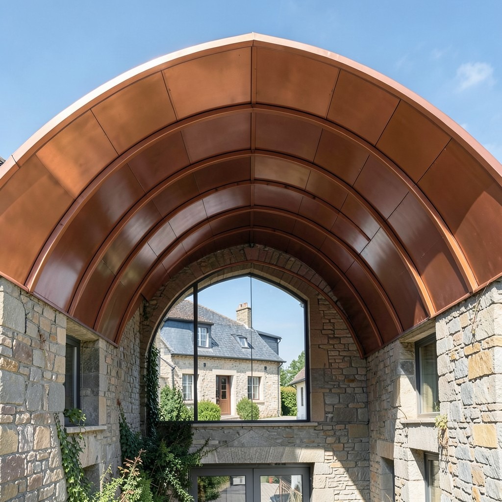
A curved roof — a roof surface formed by bending the structural members and covering materials to a radius or profile that produces a continuously curved plane rather than the flat, planar surfaces of conventional pitched roof forms — is the roof type that most directly communicates the building’s departure from conventional construction and the architect’s willingness to accept the additional structural complexity and the higher construction cost that a non-planar roof surface imposes. The curved roof is not an effect. It is a structural commitment, and the buildings that carry it most successfully are the ones whose entire architectural conception justifies the commitment rather than using the curve as a surface decoration applied to an otherwise ordinary building.
The barrel vault — a curved roof whose section is a semicircular or segmental arc running between two parallel walls — is the most structurally logical of the curved roof forms, because the arch action that distributes the roof’s load to the supporting walls at each side produces an efficient structural mechanism at the curve’s center. The barrel vault’s internal space has the specific quality of a vaulted interior — the ceiling rises from the walls to the vault’s crown in a continuous curve that changes the quality of the room below it from a contained box to an enclosed sky. That spatial quality is the barrel vault’s most immediate interior contribution.
The material for a curved roof covering must accommodate the bending of its surface without cracking, splitting, or otherwise failing at the curve’s radius. Sheet metal — zinc, copper, and steel in standing seam configurations — handles bending to almost any radius that a domestic roof structure requires. Conventional clay or concrete tiles cannot bend and must be replaced with the smaller, more flexible slate tile or with a special-curved tile format when a curved roof surface is proposed. The roofing material selection therefore constrains or enables the curve’s minimum radius, and the minimum achievable radius must be established before the curve’s profile is fixed in the design.
16. A Lantern Roof Design
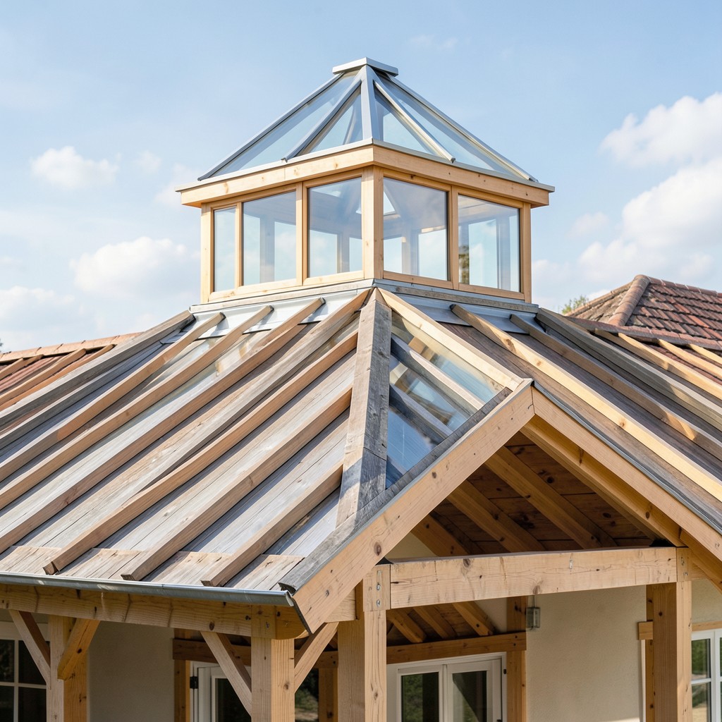
A lantern roof — a raised roof section with glazing on all vertical faces, positioned above the main roof plane to admit light from above into the space below — is the architectural device that most elegantly resolves the lighting problem of deep-plan single-storey buildings whose plan dimensions prevent adequate daylight from reaching the building’s center through perimeter windows alone. The lantern sits above the roof like a raised cupola, its glazed walls rising above the main roof’s surface and its own covering returning to the main roof level on all four sides, admitting the overhead light that only a roof penetration can deliver to a deep-plan interior.
The thermal performance of a lantern roof glazing requires the same solar gain management as any roof-level glazing element, with the additional complexity that the lantern’s vertical faces are exposed to direct solar radiation from the south and west during the afternoon hours when the combination of high solar altitude and warm air temperature produces the maximum heat gain. A lantern roof installed without solar control glazing or external shading in a south-facing orientation creates an interior greenhouse effect in summer that the building’s cooling provision must manage — an imposition on the building’s energy performance that the lantern’s daylighting benefit must honestly be weighed against.
The structural support for a lantern roof requires the roof structure below it to be designed for the lantern’s weight and the lateral wind load that the lantern’s raised glazed faces experience. A timber roof structure requires a doubled or tripled rafter arrangement at the lantern’s supporting perimeter to distribute the lantern load back to the main roof structure, and the structural calculation for this arrangement must be made by a structural engineer rather than estimated from standard rafter tables.
17. A Monitor Roof Design
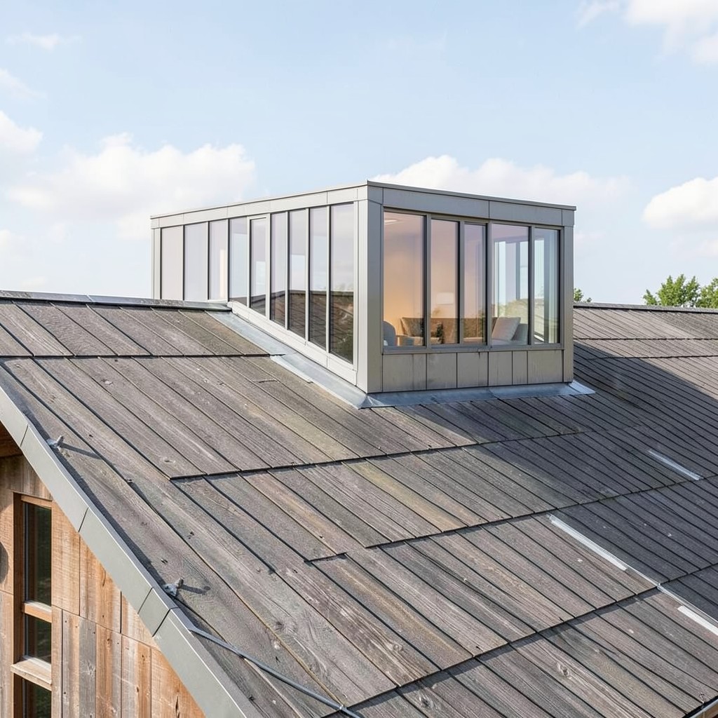
The monitor roof — a raised central section of the roof with vertical or near-vertical glazed walls running along the building’s ridge line, providing light and ventilation to the space below through the elevated opening — shares the functional logic of the sawtooth and the lantern but applies it along the full building length rather than at a point or in a cross-sectional repetition. The monitor sits as a raised box on top of the main roof’s ridge, its glazed walls admitting the high-level light and the stack-effect ventilation that the elevated position above the main roof’s thermal mass provides more effectively than any wall window at comparable floor plan depth.
The monitor roof’s ventilation performance derives from the stack effect that the elevated glazing enables: warm air rises through the interior to the monitor’s opening, creating the air movement that replaces the rising warm air with cooler air drawn in through the lower-level openings. The monitor acts as a passive ventilation chimney, and its effectiveness scales with the height difference between the floor-level inlet openings and the monitor’s ventilation outlets. A monitor roof of adequate height — the vertical glazed section at five hundred millimeters or more above the main roof’s ridge level — provides passive ventilation that reduces the building’s mechanical cooling load in summer by the amount that natural air movement can replace the air conditioning that sealed buildings require.
The proportional relationship between the monitor’s width and height and the main roof’s plan dimensions determines whether the monitor reads as an architectural feature that is scaled to the building or as an afterthought stuck on the roof regardless of proportion. A monitor whose width spans between one third and one half of the main roof’s total width reads as correctly proportioned. A monitor narrower than this proportion reads as a pipe or a small vent structure rather than as a designed roof element.
18. A Pyramid Roof Design
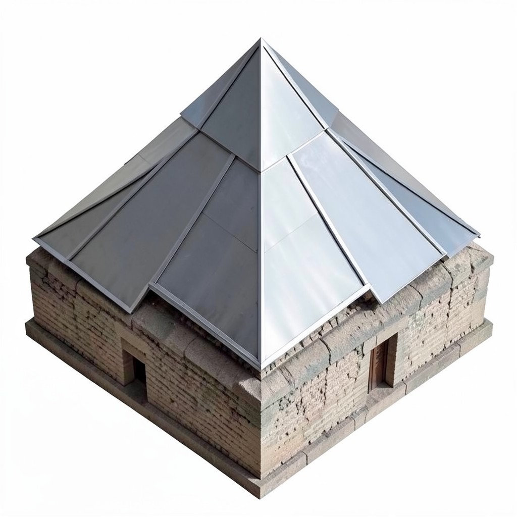
The pyramid roof — a roof form where all four sides of the building’s square or octagonal plan are covered by triangular slopes meeting at a single apex point, with no ridge — is the roof geometry that most completely encloses the building’s plan in a single geometric form, and it is the form that most ancient monumental buildings — the Egyptian pyramid most obviously, but also the pavilion roofs of Asian temple architecture and the steeple-based forms of European church architecture — have used to express the quality of completion, enclosure, and formal resolution at the building’s highest point.
The domestic pyramid roof is the natural companion of the square-plan building — the garden pavilion, the gazebo, the small agricultural outbuilding, the pool house, and the pavilion-style addition to an existing building where the extension’s square plan makes the pyramid roof the geometrically appropriate form. The pyramid over a square plan sits with the geometric certainty of a form that belongs to its base plan, and that belonging produces the specific quality of architectural completeness that a gable or hip over the same square plan cannot provide with equivalent formal resolution.
The single apex point of a pyramid roof is the detail that concentrates the greatest structural complexity and the greatest weather-exclusion challenge of the entire form. All four hip ridges converge at the apex, and the flashing, capping, or structural solution at that single convergence point must accommodate the junction of four separate roof planes in a detail whose weather performance determines the entire roof’s integrity. A poorly detailed pyramid apex is the most common water ingress point in this roof form, and the specification — whether a traditional lead-flashed timber finial, a purpose-made metal apex cap, or a contemporary folded metal solution — must be made with the specific weather performance requirement of the apex junction rather than with only its visual appearance in mind.
19. A Clerestory Roof Design
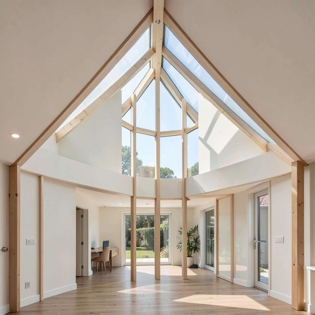
The clerestory roof — a design that raises the roof’s central section above the building’s side sections, with glazing in the raised vertical wall between the two levels — is the residential architect’s tool for bringing directional daylight deep into the interior of a single-storey building without the overhead glare and solar heat management demands of a skylight or a full glazed roof. The clerestory section admits light at a high level, above the occupant’s eye line, which distributes the admitted light across the interior ceiling and upper walls in a quality of indirect illumination that changes the room below from a laterally lit space to one that appears to be lit from above.
The orientation of the clerestory glazing determines the quality and the thermal behavior of the admitted light. A north-facing clerestory admits the consistent, diffused quality of northern sky light with minimal solar heat gain throughout the day and year — the ideal specification for a studio, a gallery, or any interior where consistent, controllable light quality is prioritised over solar warmth. A south-facing clerestory admits the higher-intensity light and the direct winter solar gain that passive solar building strategies consider desirable, but requires the same solar shading provision as any south-facing glazing to prevent summer overheating.
The structural design of the clerestory roof requires the vertical wall between the lower and upper roof levels to carry both the upper roof’s load and the lateral wind load that the clerestory’s exposed position accumulates, in addition to the opening areas of the glazed sections within it. The clerestory wall is a structural element — not a thin partition — and its cross-section and material must be specified for the structural loads it carries rather than sized for the aperture it frames.
20. A Gambrel Roof With Dormers
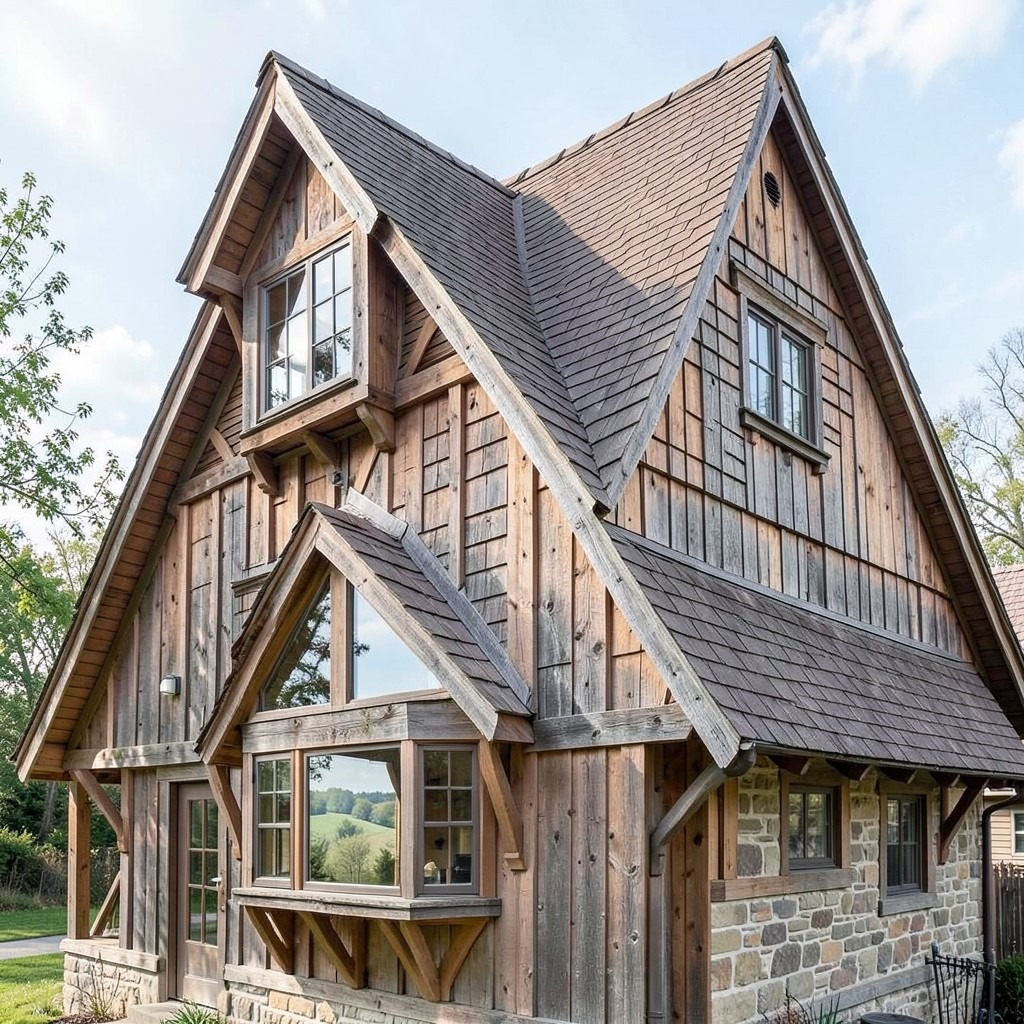
A gambrel roof with dormer windows — the American barn form with its characteristic double pitch on each side, modified by the addition of projecting dormer window structures on the upper or lower slope — is the residential roof type that most efficiently combines the gambrel’s interior volume advantage with the direct window openings that provide the roof-level rooms with the natural light, the ventilation, and the street-level visual interest that an uninterrupted gambrel surface does not provide. The dormer is not an addition to the gambrel. On a residential building, it is the gambrel’s natural companion.
The dormer window on a gambrel roof can be positioned on either the upper shallow slope or the lower steep slope, and the two positions produce different spatial experiences in the rooms they serve. A dormer on the upper slope — the shallower surface closer to the ridge — provides a window whose sill is at a higher floor level relative to the room below, producing a window that reads in the room as a high-level opening and that provides a rooftop view across the surrounding landscape rather than a ground-level outlook. A dormer on the lower steep slope — positioned at a height closer to the upper storey’s floor level — provides the window position that most closely replicates the standard upper-floor window experience in terms of outlook and light quality.
The dormer’s structural relationship with the gambrel requires the rafter arrangement at the dormer’s position to be modified to carry the dormer’s weight and to transfer the loads around the opening to the adjacent structural members — the doubled trimmer rafters at each side of the dormer opening and the header rafter spanning between them at the dormer’s top. This structural modification is the carpentry complexity that makes dormer addition to an existing gambrel more disruptive than its visual simplicity suggests, and it must be designed by a structural engineer for the specific rafter spacing, span, and loading conditions of the existing roof.
21. A Folded Plate Roof Design
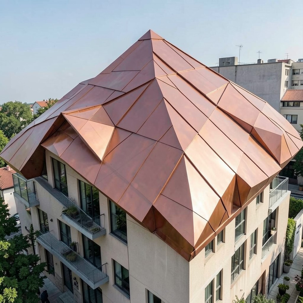
The folded plate roof — a structural and visual form composed of flat planar surfaces arranged at varying angles to each other, creating the faceted, origami-like geometry that structural engineers developed in the mid-twentieth century as a means of achieving structural depth and rigidity from relatively thin flat-plane elements — is the roof type that most directly expresses the relationship between structural logic and architectural form. The folds are not decorative. Each fold is a structural depth element — a change in direction that converts a flat, flexible plate into a stiff structural member through the same geometric principle that a sheet of paper is transformed from a flexible flat sheet into a self-supporting beam when folded along its length.
The visual character of a folded plate roof is determined by the number of folds, the angles between the planar segments, and the relationship between the roof geometry and the building plan below it. A simple three-panel fold — two angled outer planes meeting a central horizontal panel at ridge folds — reads as a refined, angular gable. A complex multi-fold roof whose faceted surface breaks the building’s outline into a series of angular planes at different pitches reads as a sculptural form that the building’s walls support rather than as a conventional roof covering. The design discipline of the folded plate is that every fold must be structurally justified — each angle change must contribute to the structural performance — or the form reads as arbitrary rather than resolved.
The material for a folded plate roof is almost always metal — zinc, copper, aluminium, or steel — because the fold geometry requires a covering material that can be fabricated to the precise angles of the faceted surface and that performs at the exposed ridges, valleys, and hip details that every fold produces. The fold junctions are the most weather-exposed details of the folded plate roof, and the metal fabrication standard at these joints — the accuracy of the folding, the continuity of the seam, and the flashings at each angular junction — is the detail quality on which the roof’s weather performance entirely depends.
22. A Parapet Roof Design
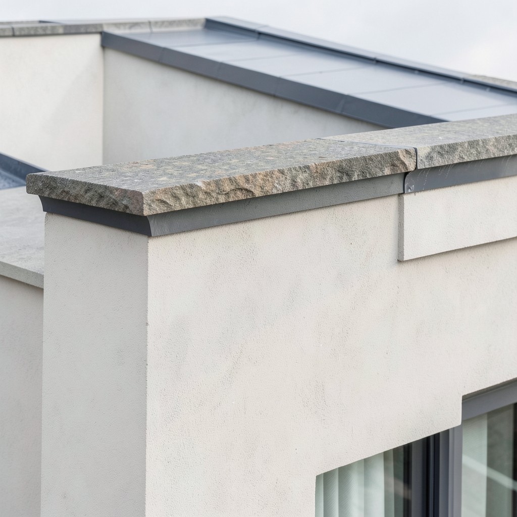
A parapet roof — any roof form where the wall of the building extends above the roof surface to form a parapet wall that conceals the roof edge from the street or the observer at ground level — is the roof design detail that most completely disguises the building’s roof form from external view and that produces the specific flat-topped silhouette associated with the classical urban street facade, the Georgian terrace, and the contemporary minimalist building that wants its roofline to read as a clean horizontal plane rather than as a pitched or gabled form. The parapet hides the roof. That is its function, and it serves that function with architectural consequences for the building’s entire character.
The weather performance of a parapet roof is governed by the parapet’s coping — the weather-excluding cap that covers the parapet wall’s top surface and prevents rainwater from penetrating the wall through its uppermost exposed course. A coping in natural stone, cast stone, or metal provides the weather cap whose overhang and drip detail directs water away from the wall face below it, preventing the staining, saturation, and eventual frost damage that an inadequately coped parapet accumulates through the cycles of wetting and drying that exposed wall tops experience in temperate climates. The coping’s drip detail — a groove or projection on the coping’s underside that breaks the capillary path between the coping soffit and the wall face — is the detail that determines whether the coping performs its weather function or allows water to track back onto the wall.
The parapet’s relationship with the roof structure below it creates the junction at which water ingress most commonly occurs in parapet-roofed buildings — the upstand where the waterproof roof membrane turns up the parapet face, the flashing that covers this upstand, and the junction between the flashing and the coping above it. This three-element junction must be detailed and installed to a standard that provides continuous weather resistance from the roof membrane through the flashing to the coping, with no gap at the transitions between elements.
23. A Gull Wing Roof Design
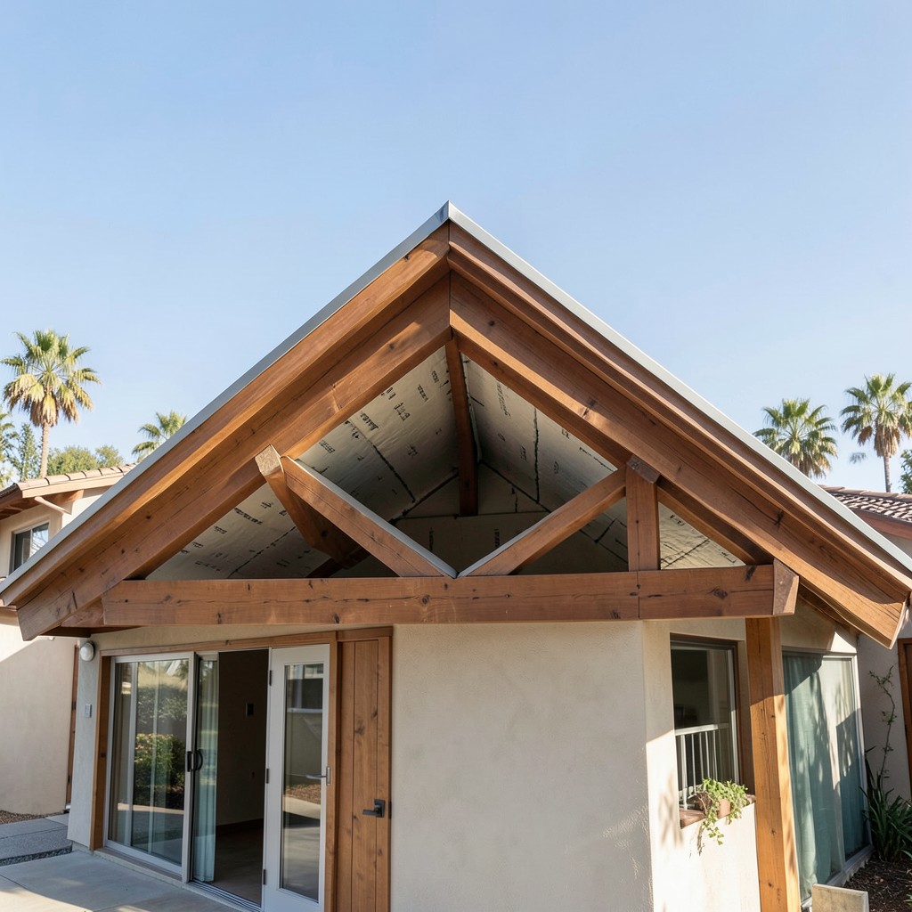
The gull wing roof — a roof form whose two sloping surfaces angle upward from the eaves rather than downward, meeting at a raised valley ridge in the center and producing the soaring, wing-spread profile that gives the form its name — is the mid-century modernist roof type most associated with the southern California residential tradition and with the specific architectural ambition of a building that wants its roofline to express lift, flight, and the opposition of structural convention rather than the settled, downward gravity of the conventional pitched roof. The gull wing roof says something specific about the building’s relationship with its setting. The question is whether what it says is what the building needs.
The drainage challenge of the gull wing is the same fundamental problem as the butterfly roof’s valley — the central channel collects water from both roof planes and must discharge it reliably from the building’s perimeter at adequate capacity. The difference from the butterfly is that the gull wing’s valley ridge is at the building’s highest point rather than its lowest, which means the drainage path from the valley to the eave outlet crosses the entire lower slope of each roof plane. The valley gutter’s fall toward the drainage outlet must be provided within the gull wing’s geometry, and the structural depth of the valley zone must be sufficient to carry both the valley gutter and the insulation layer without compromising the roof’s thermal performance.
The structural system for a gull wing roof — the element that holds the two rising planes in their upward-angled orientation against the downward load of the roof’s weight and the uplift load of wind on the exposed undersides of the raised wings — is the engineering challenge that distinguishes the gull wing from all other roof forms. The underside of the gull wing is exposed to wind uplift that the downward-sloping surfaces of conventional roofs resist through the roof structure’s direct bearing on the walls. The gull wing’s upward-sloping surface presents its underside to the wind in a condition more similar to a wing than a roof, and the fixing of that surface to the building below it must resist the uplift forces that the aerodynamic geometry generates.
24. A Zinc Roof Design
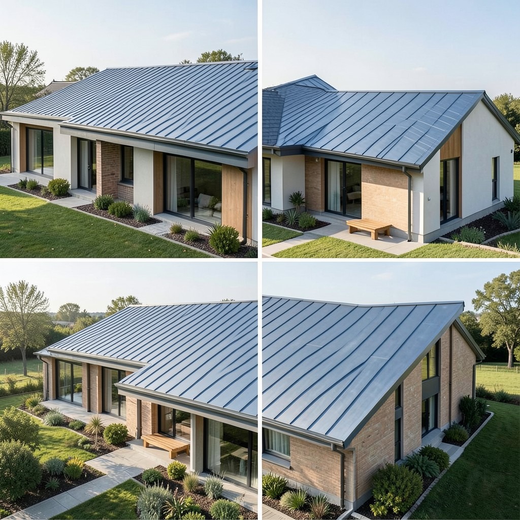
Zinc as a roofing material occupies a specific position in the material hierarchy of contemporary architecture — above the commodity materials of asphalt and concrete tile in both longevity and design quality, and below the premium of copper in cost and patina drama, providing the specific combination of accessible budget and genuine architectural quality that makes it the material of choice for serious residential architecture that does not have the budget for copper but refuses the visual compromise of cheaper alternatives. The zinc roof is the roof of the designer who has thought about the building’s thirty-year future as well as its opening day.
The two principal zinc roofing systems — standing seam and flat-seam — produce different surface characters and are suited to different roof forms and pitches. The standing seam system, with its raised longitudinal seams running parallel to the slope, provides the textured, directional surface that reads as a designed material installation from a distance and provides the panel movement accommodation that thermal expansion across long roof dimensions requires. The flat-seam system, with its soldered or folded flat seams on both the longitudinal and the lateral joints, provides the smooth, continuous surface that low-pitch and curved roof applications require, where the standing seam’s raised profile would create water collection at the lateral seams.
The zinc roof’s color evolution — from the bright, slightly blue-tinted metallic silver of new zinc through the progressive darkening and matting of the first years of weathering to the stable blue-grey of fully developed zinc patina — is the material’s most distinctive quality and the one that most rewards the long view of the building’s appearance over its decades of service. The zinc roof on a building at ten years has acquired the settled, muted tone that the bright new installation promised but could not yet deliver, and at twenty-five years its blue-grey surface reads as the natural material color of a building that has been in its landscape long enough to belong there. That quality of belonging is the zinc roof’s most valuable contribution to the buildings it covers, and it cannot be accelerated beyond the weathering that time alone provides.
25. A Copper Roof Design
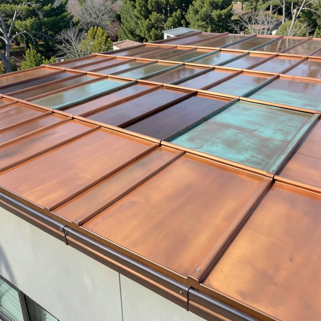
Copper is the roof material that architects reach for when the building warrants the expenditure of a premium specification and the client understands that the investment will reward the building’s character more generously with every decade that passes. No other roofing material develops its appearance over time with the consistency, the beauty, or the range of copper’s patination — from the bright orange-brown of fresh installation through the darkening chocolate of early weathering to the turquoise-green verdigris that forty-plus years of atmospheric exposure produces on surfaces with adequate moisture contact. The copper roof does not age. It deepens.
The standing seam copper roof is the standard specification for residential applications, with panel widths of five hundred to six hundred millimeters providing the visual scale that suits domestic building proportions. The copper must be fixed to allow thermal movement without restraint — copper expands by approximately one millimeter per meter across a sixty-degree temperature range — and the standing seam fixing clips that engage the raised seams must slide within the seam rather than rigidly fixing the panel to the substrate. A copper roof fixed without adequate thermal movement accommodation develops the oil-canning — the buckling of the panel surface between fixing points — that reads as a material failure even when it is a fixing design failure.
Pre-patinated copper — factory-treated to the blue-grey or turquoise surface of naturally weathered copper — is available for installations where the building’s design requires the aged material character immediately rather than after the natural patination period. The factory process applies the patina through chemical treatment of the copper surface and produces a color that is visually accurate but whose tone can vary slightly from panel to panel in a way that natural patination — which varies across a single surface depending on orientation, exposure, and moisture history — actually also produces. The pre-patinated copper roof looks like aged copper because the treatment is genuine chemistry applied to genuine copper, not a surface coating.
26. A Corrugated Metal Roof Design
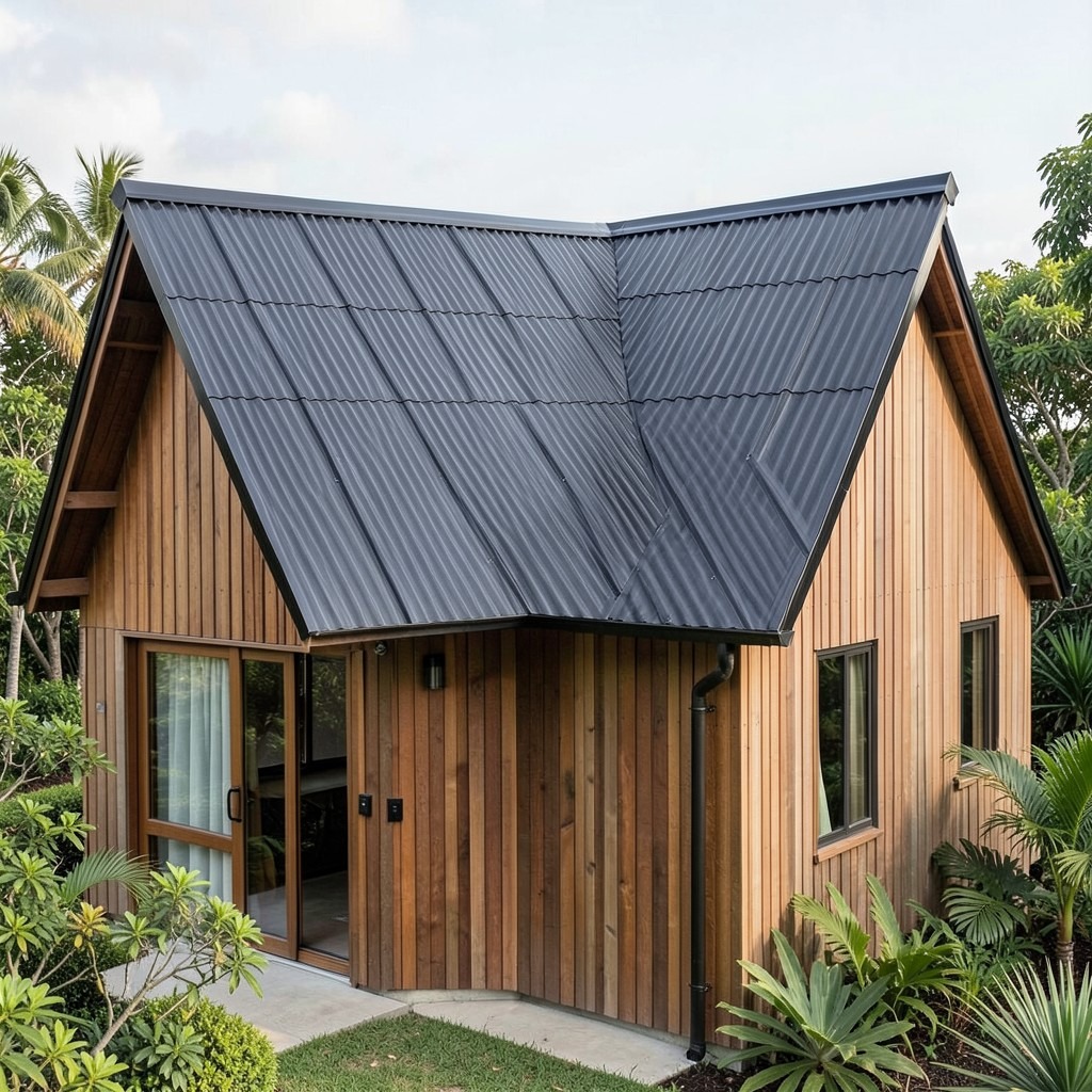
Corrugated metal roofing — the sinusoidal or trapezoidal profile sheet material in steel, aluminium, or zinc-coated steel — carries the specific cultural weight of the agricultural building, the industrial shed, the rural workshop, and the vernacular corrugated iron tradition that spread across the British colonial world as the cheapest, lightest, most transportable roof covering available at a historical moment when building materials traveled by ship. That heritage is now the material’s design asset rather than its limitation: the corrugated metal roof on a contemporary residential building brings the honest industrial quality of the agricultural material into a domestic context with the specific design tension between raw material character and considered architectural application that produces some of the most interesting contemporary residential architecture.
The profile depth of corrugated metal sheet — the height between the crest and the trough of the corrugation — determines both the structural spanning capacity and the visual scale of the roof surface. A deep-profile trapezoidal sheet in a seventy-two millimeter profile spans the structural purlin spacings typical of domestic roof construction without additional structural members between the purlins, providing the cost efficiency of a material whose structural performance reduces the supporting structure’s complexity. A shallower sinusoidal corrugated profile at thirty to thirty-five millimeters provides the traditional corrugated iron visual character at a structural spanning capacity appropriate to closer purlin spacing.
The color and coating of a steel corrugated roof — the polyester or plastisol paint coating applied over the galvanized steel substrate — provides both the weather protection and the color range that make the material adaptable to a broader range of design contexts than its raw galvanized appearance would allow. A black polyester-coated corrugated steel roof on a contemporary timber-clad building reads as a designed material combination rather than as a budget covering applied without thought. The same material in its raw galvanized finish reads as agricultural or industrial — not wrong, but a more specific design statement that commits the building to a narrower range of architectural associations.
27. A Roof Terrace Design
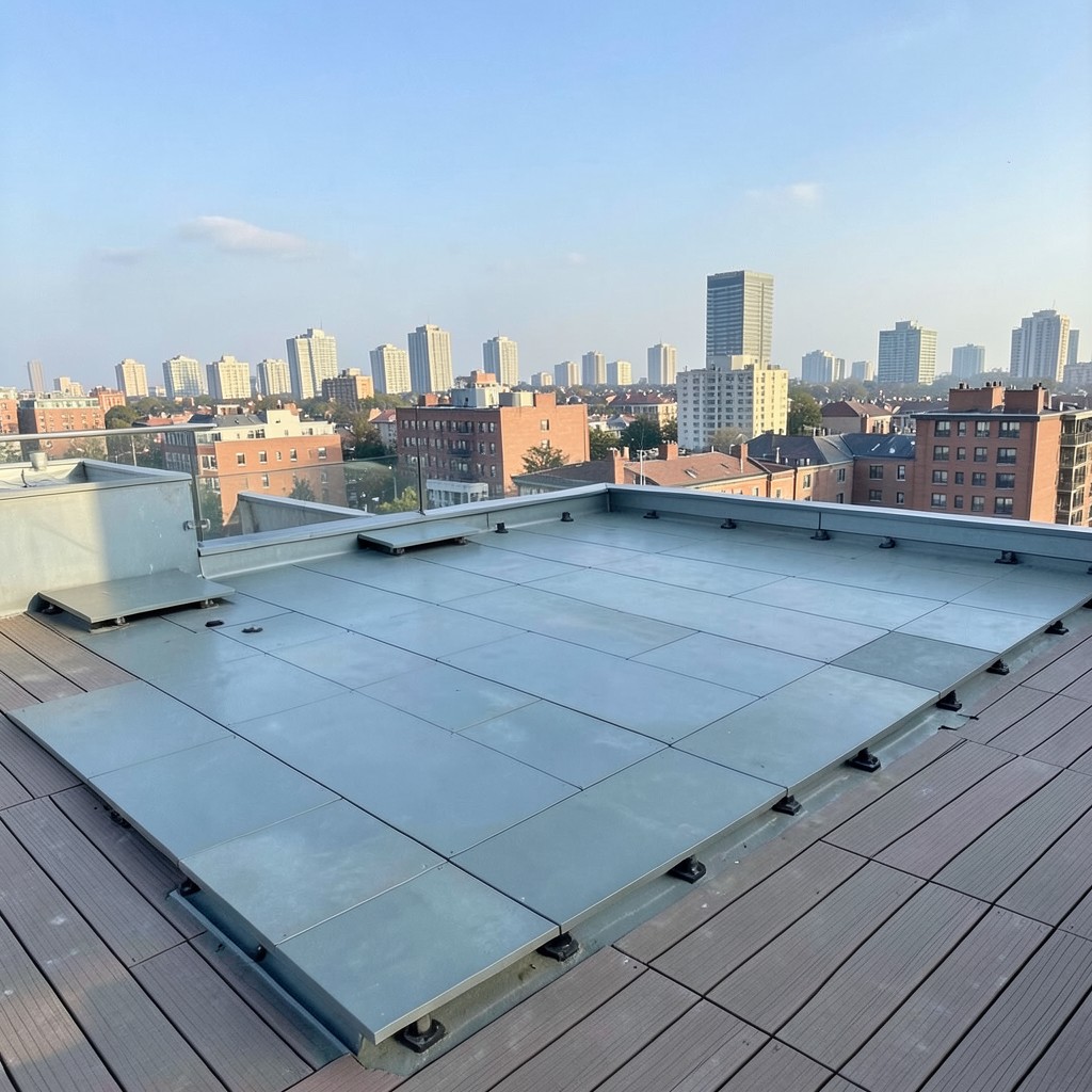
The roof terrace — an outdoor living space created on the flat or accessible roof of a building, designed and furnished as an additional external room — converts the building’s largest impermeable horizontal surface from a weather exclusion plane that no one visits into the most elevated and most private outdoor space the property can provide. The roof terrace in an urban building is the outdoor space that is above the noise, above the overlooking sight lines of neighboring ground floors, and above the ground-level constraints of a small or overshadowed garden. It provides a quality of light and sky connection that no ground-level outdoor space in a dense urban setting can match.
The waterproof deck surface of a roof terrace — the paving, the timber decking, or the composite deck board installed over the roof’s waterproof membrane — must be installed in a way that provides direct maintenance access to the membrane below without requiring the demolition of the entire deck surface. Pedestal-mounted paving systems — paving slabs or porcelain tiles lifted from the membrane surface on adjustable plastic pedestals — provide the access requirement through the ability to lift individual slabs without disturbing the surrounding surface, while simultaneously allowing the drainage path between the membrane and the deck surface to manage storm water without the deck surface becoming a water retaining plane above the membrane.
The structural roof loading for a terrace appearance over time. The blue-grey patina that zinc develops after full weathering is not a degradation of the material — it is the formation of a protective zinc carbonate layer that stabilises the surface and protects the zinc beneath from further corrosion, extending the roof’s service life to eighty years or more in temperate climates. Specifying a pre-patinated zinc — a factory-treated surface that has been chemically converted to the stable patina state before installation — provides the aged appearance from the first day and removes the transitional weathering period during which the zinc surface changes color unevenly and reads as installation-new rather than design-mature.
28. A Reclaimed Tile Roof Design
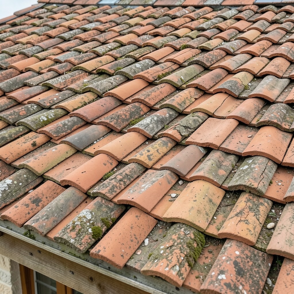
A roof covered in reclaimed clay tiles — original handmade or machine-made clay tiles salvaged from demolished buildings, sorted, cleaned, and relaid on a new or replacement roof — provides the building with a material authenticity that no new tile, regardless of how convincingly it is manufactured to simulate age, can replicate. The reclaimed tile carries the physical evidence of its previous service: the color variation from decades of weathering, the slight surface texture of the original firing process, the occasional moss ghost where lichen colonised a previous position, and the aggregate of small material differences between individual tiles that handmade production and genuine ageing produce and factory production cannot.
The practical challenge of a reclaimed tile specification begins with sourcing adequate quantity in a consistent format. Reclaimed clay tiles are available from salvage yards and demolition contractors in quantities that depend entirely on the availability of compatible material from buildings being demolished at the time the specification is being made — a supply condition that cannot be guaranteed in the way that a manufactured tile’s delivery lead time can be committed to. The specification must identify the tile format — the head lap dimension, the width, and the nail hole position — required for the existing or new roof structure’s gauge, and must source sufficient matching tiles plus a working surplus of twenty percent before the installation program begins.
The structural implication of a reclaimed tile roof is the same as for new clay plain tiles — the roof structure must be designed for the weight of clay tile at the appropriate dead load figure, which exceeds the loading of lightweight concrete tile and significantly exceeds the loading of asphalt shingle or metal sheet coverings. A roof structure originally designed for a lightweight covering that is being re-roofed in reclaimed clay tiles requires a structural assessment before the tile specification is confirmed, because the additional dead load may require strengthening of the rafter or purlin sections to maintain adequate structural safety margins.
29. A Concrete Tile Roof Design
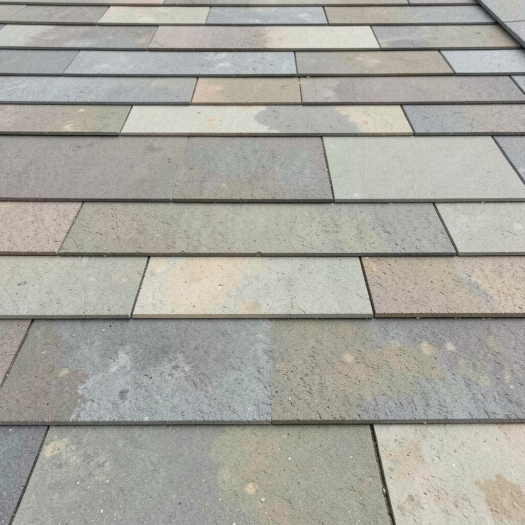
Concrete roof tiles occupy the middle ground of the residential roofing market — more durable than asphalt shingle, less expensive than clay or slate, available in a profile range that covers most of the aesthetic territory of the traditional tile types they are frequently specified to approximate — and that middle ground position defines both their commercial dominance and their design limitation. A concrete tile roof is a perfectly competent roof covering. It is rarely a design distinction. The building that deserves a better roof covering than it has received and that carries a concrete interlocking tile in a simulated slate colour is a building whose roof specification was made on cost grounds, and the concession reads.
That said, the concrete tile at its best — a flat concrete plain tile in a carefully selected natural stone colour, laid at the gauge and head lap that the tile format requires — provides a roof surface with the texture and the visual depth of a material that has substance rather than thinness. The flat plain concrete tile in a weathered grey or a warm buff reads better than the profiled interlocking concrete tile in a simulated heritage colour, because the flat format’s restraint allows the material’s own surface character — the slight aggregate texture, the colour variation between tiles from different production batches — to provide the visual interest rather than the profile’s imposed pattern.
The longevity of a concrete tile roof is the specification parameter most frequently overstated by manufacturers and most honestly evaluated by the building’s maintenance record over its first thirty years. Concrete tiles are not equivalent to clay or slate in service life — the cement matrix that binds the aggregate gradually carbonates and loses strength over decades, and the tile surface coating that provides the initial colour fades under UV exposure in a way that clay’s fired glaze does not. A concrete tile roof specified for a twenty-five to thirty year service life before replacement is a realistic expectation; a specification that positions concrete tile as equivalent to clay or natural slate in longevity is not.
30. A Polycarbonate Roof Design

A polycarbonate roof — a glazed roof covering formed from multiwall or solid polycarbonate sheets in a supporting aluminum or timber sub-frame — is the material choice that provides the maximum light transmission of any opaque or translucent roof covering at the lowest weight and cost, and it is the specification that most domestic lean-to extensions, conservatories, and covered outdoor structures receive when the design brief is natural light and the budget is constrained. The polycarbonate roof delivers on both requirements. Its other performance parameters — thermal insulation, acoustic performance, UV stability, and the visual quality of the light it admits — are where the honest conversation about its limitations begins.
The multiwall polycarbonate sheet — a twin-wall or triple-wall extruded profile with air chambers between the faces — provides the thermal insulation that solid polycarbonate lacks, with the twin-wall achieving a U-value of approximately 3.3 W/m²K and the triple-wall providing a modest improvement to around 2.1 W/m²K. Neither value approaches the thermal performance of a double-glazed unit, which achieves 1.0 to 1.4 W/m²K depending on specification, which means a polycarbonate-roofed extension loses heat at a rate that makes it a seasonal space rather than a year-round room unless a supplementary heating system is provided for the cold months.
The UV degradation of polycarbonate over time is the performance parameter that most affects the material’s service life and the visual quality of the light it admits through the course of that life. Quality polycarbonate sheets carry a UV-resistant coating on the external face that retards the yellowing and hazing that uncoated polycarbonate develops under prolonged sun exposure, but the coating’s effectiveness diminishes over ten to fifteen years and the sheet’s light transmission quality progressively reduces from the clarity of new installation toward the amber-tinted diffusion of aged polycarbonate. Replacement rather than maintenance is the response to aged polycarbonate, which makes the true ten to fifteen year replacement cost part of the honest polycarbonate roof specification.
31. A Fibre Cement Roof Tile Design
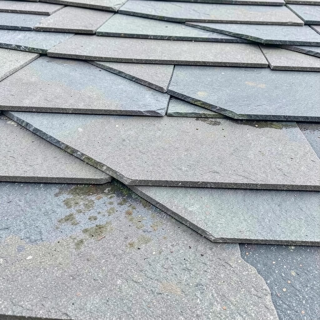
Fibre cement roof tiles — a compressed mixture of cement, cellulose fibre, and mineral pigment formed into flat slates or profiled tiles — provide the visual character of natural slate or plain clay tile at a weight and cost that falls between the premium natural materials and the budget concrete alternative, and their performance record in temperate climates is sufficiently long-established to allow specification with confidence rather than optimism. The fibre cement flat slate — a format sized and profiled to replicate the dimensions of a natural slate — is the material used most widely in domestic construction where planning consent conditions require a natural slate appearance but the budget does not support the natural material.
The colour stability of fibre cement tiles improves significantly over the mineral granule and paint coatings used on comparable concrete products. The mineral pigment used in quality fibre cement slate production is incorporated throughout the material body rather than applied as a surface coating, which means the colour remains consistent as the surface weathers rather than fading from the coated surface as UV exposure and rainfall combine to erode the coating layer. The practical consequence of this colour stability is a roof that maintains its appearance consistently through the twenty to thirty year service life rather than requiring coating treatment at ten-year intervals to restore the original colour.
The installation of fibre cement flat slates follows the same double-lap principle as natural slate — each course overlapping the course two below it by the head lap dimension — and requires the same specification attention to the appropriate head lap for the roof’s pitch and its exposure zone as natural slate installation does. The common installation error with fibre cement slate is the application of a head lap appropriate for a sheltered low-exposure condition on a roof in a high-exposure coastal or upland location, where the wind-driven rain penetration through an inadequate head lap produces the persistent damp conditions in the roof space that misattribute the fibre cement tile’s performance failure to the material rather than to the specification.
32. A Bitumen Shingle Roof Design
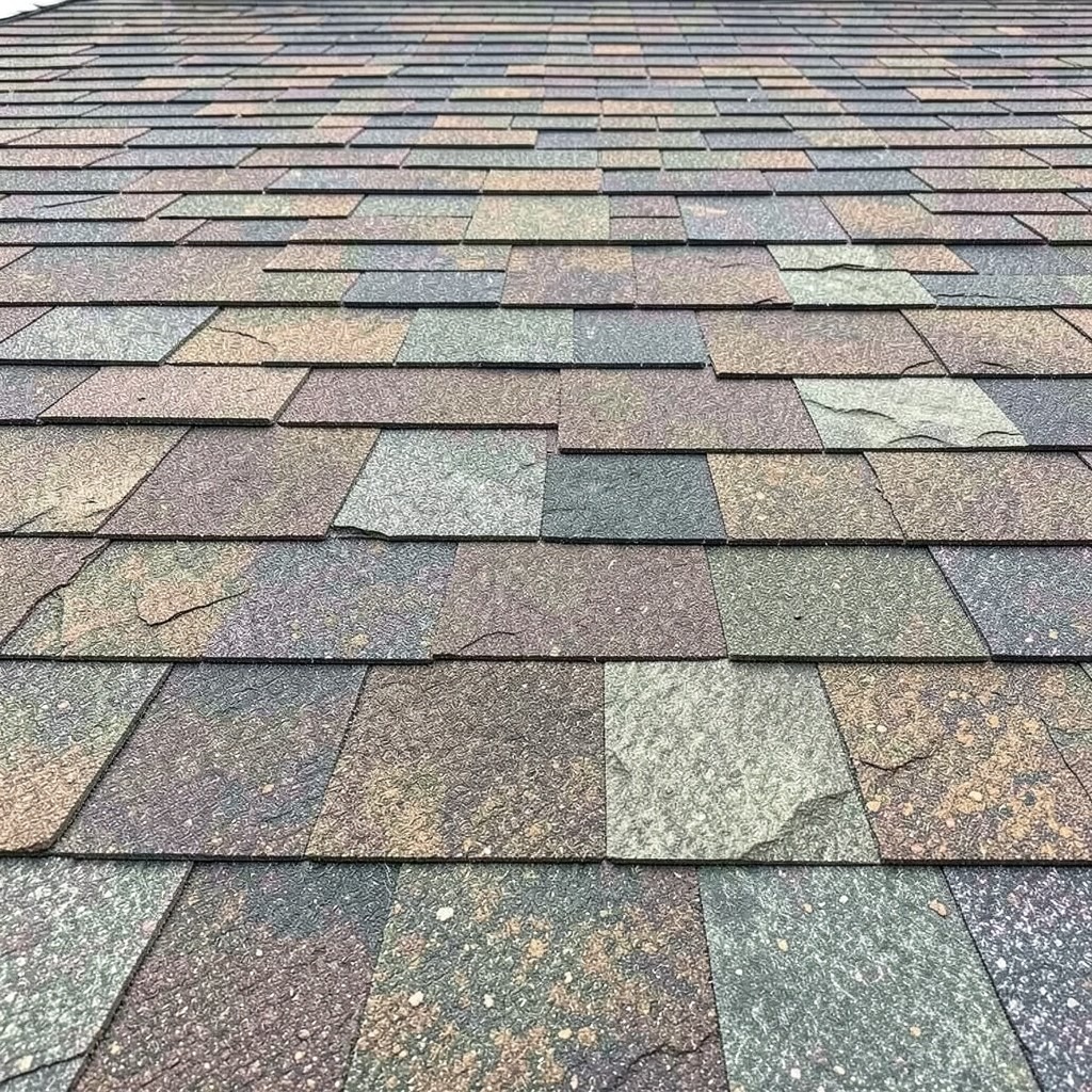
Bitumen shingles — the asphalt-impregnated fiberglass or organic felt mat tiles, surfaced with mineral granules in a range of colours and profiles, that cover the majority of residential roofs in North America and a growing proportion of domestic roofs in northern Europe — are the roof covering whose market penetration most significantly exceeds their design quality, and that disproportion is the result of their installation simplicity, their low cost, and the marketing success of an industry that has effectively positioned a serviceable but unremarkable material as the default residential roof specification for a large part of the global housing market.
The architectural shingle — a heavier, multi-layer bitumen shingle that produces a dimensional, textured surface by laminating multiple layers of the base material with deliberately varied mineral granule patterns — represents the design ambition of the bitumen shingle category and is the format worth considering when the specification options are limited to this material type. The architectural shingle’s dimensional surface reads as having depth and texture from a street-level viewing distance that the three-tab shingle’s flat, uniform surface cannot approximate, and the color range available in the premium architectural shingle formats includes the subtle blended tones of natural weathered slate and aged wood shake that suit a building whose architectural character the shingle must support rather than undermine.
The service life of a standard bitumen shingle roof — twenty to twenty-five years before replacement in a temperate climate without extreme temperature cycling — is the parameter that most honestly separates this material from the clay, slate, and metal alternatives whose service lives are measured in decades rather than in tens of years. The replacement cost of a bitumen shingle roof every twenty-five years, accumulated across a building’s hundred-year life, exceeds the one-time installation cost of a natural slate or standing seam metal roof whose service life covers the same period without replacement. The lifetime cost calculation is the context that the initial installation cost comparison consistently omits.
33. A Wooden Shingle or Shake Roof Design
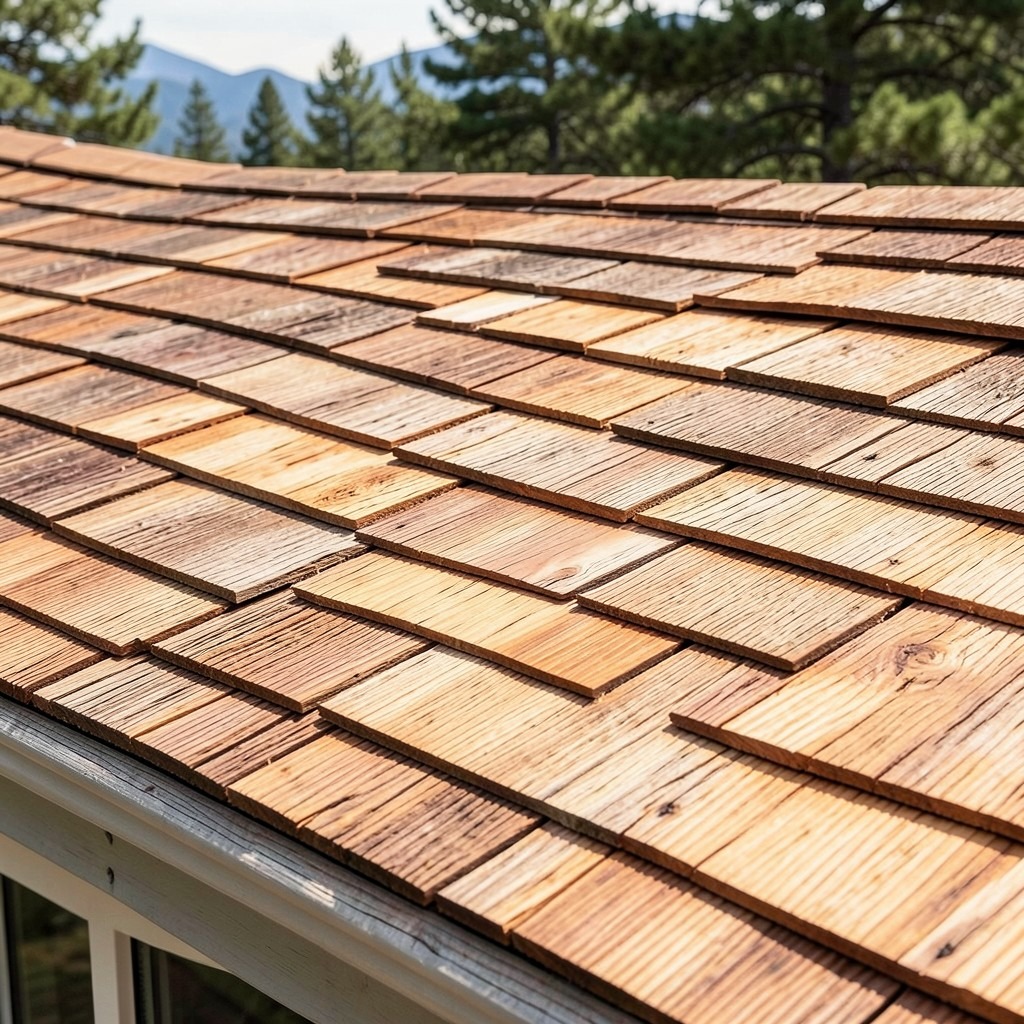
Cedar wood shingles and shakes — the split or sawn western red cedar tiles that cover roofs in the North American Pacific Northwest tradition and that have been adopted by residential architecture internationally for their warm, organic material quality — are the roof covering that produces the most natural, handcrafted material character of any residential roofing option and the one that requires the most consistent maintenance discipline to perform to its potential service life. The cedar shake roof that is properly maintained — cleaned of debris, treated with preservative and biocide every five to seven years, and kept free of the moss and lichen growth that retains moisture against the wood surface — provides a service life of thirty to fifty years. The cedar shake roof that is installed and left unattended degrades in half that time.
The split cedar shake has a more textured, irregular surface than the sawn cedar shingle because the splitting process follows the wood’s natural grain rather than cutting across it, producing a surface whose ridges and valleys reflect the fibrous structure of the cedar rather than the smooth, consistent face that the saw produces. That natural texture is the shake’s most distinctive aesthetic quality and the characteristic that gives the cedar shake roof the specific organic character that the sawn shingle approximates more finely but with less material drama. The choice between shake and shingle is a choice between two different positions on the spectrum between raw material character and refined craftsmanship.
The fire resistance of cedar shake and shingle roofs is the specification concern that building regulations in fire-prone regions increasingly address through requirements for fire-retardant treated wood or for fire-resistant underlays beneath the wood surface. Untreated cedar is a combustible material, and in regions where wildfire or urban fire spread is a genuine risk, the cedar roof’s combustibility requires either the treatment or the material substitution that the regulatory environment specifies. The fire-retardant treated cedar provides a Class B fire rating in most testing protocols — adequate for most residential applications outside the highest fire-risk zones where Class A is required.
34. A Sedum and Wildflower Green Roof
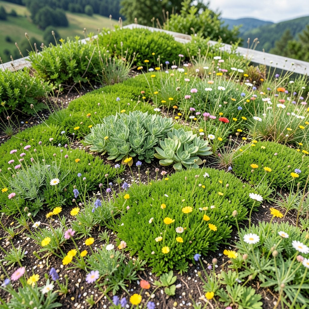
A sedum and wildflower green roof — the planted roof covering that combines the drought-tolerant succulent coverage of a standard sedum extensive roof with the seasonal wildflower interest and the additional ecological value of native annual and perennial species — is the green roof specification that most closely connects the roof’s planted surface to the ecology of the surrounding landscape rather than to the generic sedum species that the standard extensive green roof product delivers without regional ecological specificity. The sedum and wildflower combination is the roof that looks designed in summer and ecologically alive in spring, and it is the specification worth pursuing when the green roof’s contribution to garden biodiversity is as important as its structural performance.
The wildflower component of a sedum and wildflower roof requires the establishment conditions that the standard sedum carpet does not provide — specifically, areas of the growing medium surface that are not pre-colonised by sedum, into which wildflower seeds can germinate and establish before the sedum’s lateral spread closes the gaps. The installation approach that achieves this uses a sedum carpet with deliberate wildflower seed incorporation in the growing medium beneath, supplemented by the hand-broadcast sowing of native wildflower species at installation and relying on the species that establish from seed to colonise the gaps in the sedum coverage before the sedum’s growth rate fills them.
The maintenance of a sedum and wildflower roof through its first three years requires the management approach of a wildflower meadow at minimal elevation: the monitoring and removal of invasive species — particularly the pioneer annual weeds that colonise open growing medium surfaces in the first growing season — and the supplementary sowing of any wildflower species whose establishment from the initial sowing was inadequate. After the third growing season, the planted community is self-sustaining in the ecological balance that the species composition and the growing medium fertility level have reached, and the roof’s annual maintenance reduces to the inspection and drainage clearance that any green roof requires.
35. A Rainwater Harvesting Roof Design
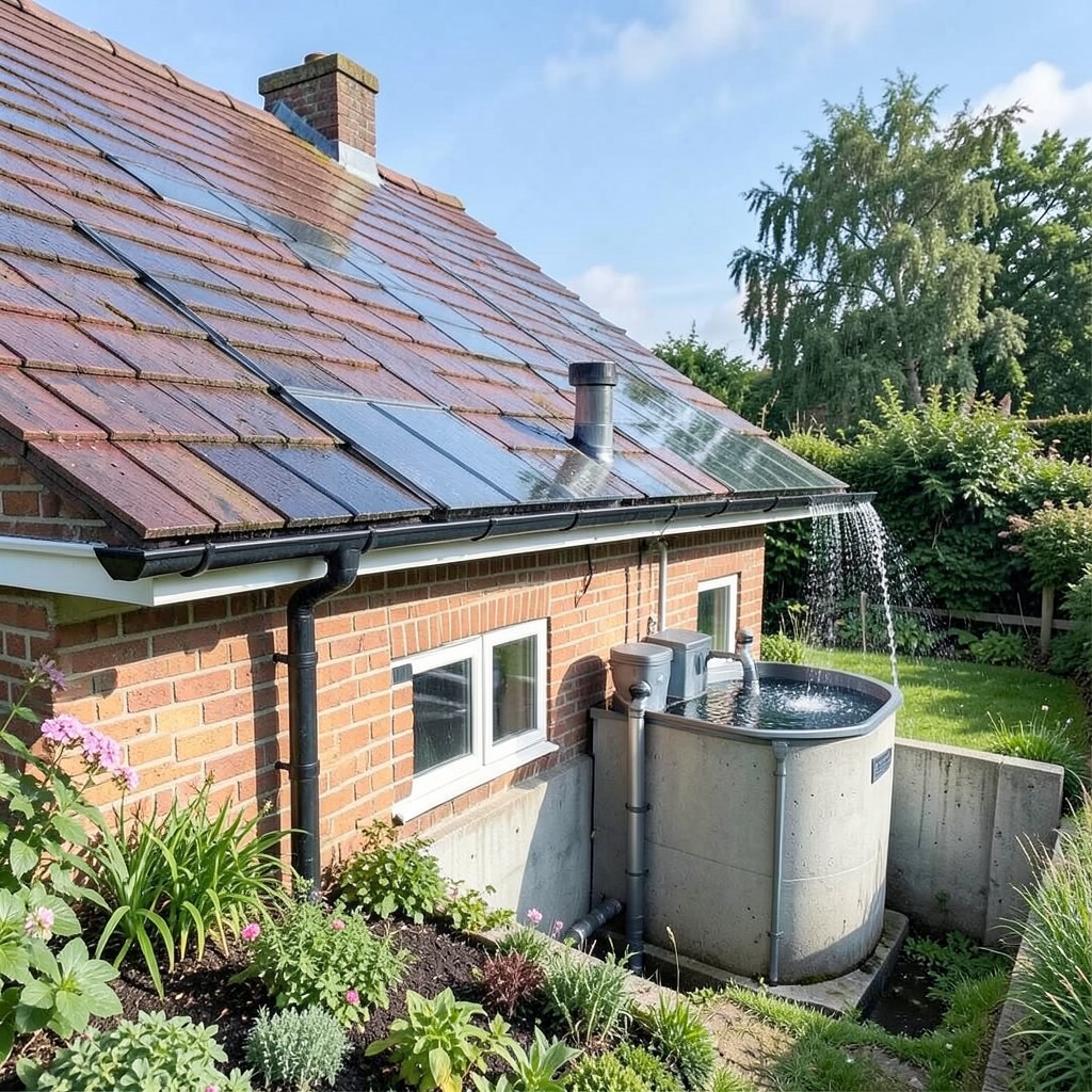
The roof as a rainwater collection system — designed from the beginning with the catchment area, the fall direction, the gutter specification, and the storage provision calculated as a coordinated water management infrastructure rather than as weather exclusion alone — is the roof design direction that converts the building’s largest horizontal surface from a passive water-shedding plane into an active water resource. A standard domestic roof in a temperate climate with an annual rainfall of six hundred millimeters generates a rainwater harvest of approximately sixty liters per square meter of plan area per month in the wetter half of the year — enough to supply the majority of a household’s non-potable water requirements from the garden irrigation to the toilet flushing.
The gutter and downpipe specification for a rainwater harvesting roof must be sized for the collection function rather than simply for the drainage function that most gutter sizing calculations address. A gutter sized to drain the roof’s calculated peak rainfall intensity without overflow is correctly sized for drainage. A gutter sized to collect and direct the maximum proportion of the roof’s total annual rainfall toward the storage tank requires the additional specification of the first-flush diverter — a device that diverts the first few liters of rainfall, which carry the roof’s accumulated dust, bird deposits, and atmospheric pollution, to waste while directing the cleaner subsequent rainfall to the storage tank.
The storage tank specification — its volume, its location, and its distribution system — determines the harvesting system’s practical contribution to the household’s water budget. A below-ground tank in reinforced GRP or concrete, positioned below the garden surface adjacent to the building, provides the storage volume in a location where the water temperature remains cool and consistent, reducing the biological growth that warm storage conditions accelerate. A storage volume of three thousand liters — achievable in a modest below-ground installation — provides the buffer between supply and demand that converts the variable rainfall pattern of a temperate climate into a consistent water source for garden and toilet use.
36. A Photovoltaic Roof Tile Integration
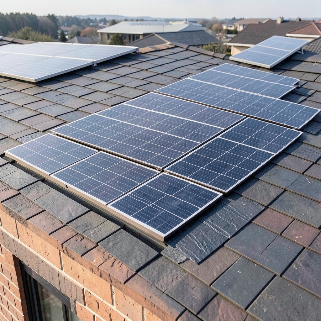
The integration of photovoltaic generation directly into the roof tile — replacing a section of the conventional roof covering with active generating tiles that perform the weather exclusion function of the standard tile while generating electricity from their upper surface — is the roof design solution that produces the cleanest visual integration of solar energy generation into the building envelope of any solar roof technology available, and it is the solution whose practical performance characteristics have developed significantly as the technology has matured from its early, expensive, and relatively inefficient first generation into the current product range.
The generating efficiency of integrated photovoltaic roof tiles — expressed as watts of peak generating capacity per square meter of installed tile surface — is lower than the equivalent area of optimally tilted, conventionally mounted solar panel. The integrated tile accepts the roof’s fixed pitch and orientation as its generating conditions rather than allowing the panel mounting system to optimise the tilt angle for maximum generation. The efficiency reduction relative to optimised panel mounting is typically fifteen to twenty-five percent, and this reduction is the honest performance cost of the integrated aesthetic — a cost that the building whose architectural quality the visual integration protects will consider worthwhile, and that the building whose primary objective is maximum electricity generation at minimum cost will not.
The roof covering around the photovoltaic tile sections must be specified for compatibility with the tile system’s module dimensions, fixing centres, and weathering details at the junctions between the active tiles and the conventional covering. Most photovoltaic tile systems are designed to interface with specific conventional tile formats from the same manufacturer, and the specification of a different conventional tile around a photovoltaic tile system introduces the junction detailing complexity that the system manufacturer’s compatibility testing has not validated. The safest specification uses the manufacturer’s complete system — both the photovoltaic tiles and the surrounding conventional tiles — rather than mixing systems at the junction.
37. A Tiled Hip and Valley Roof Design
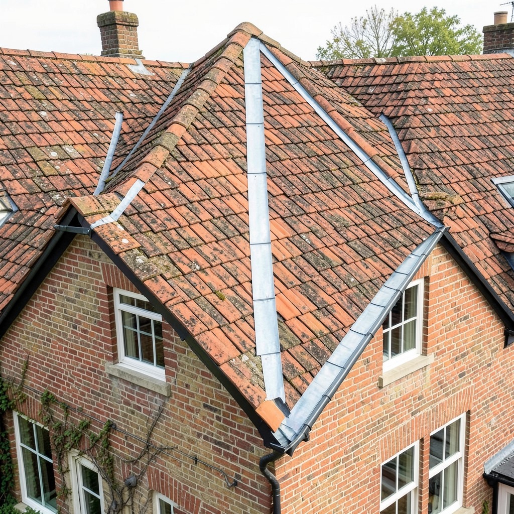
A tiled hip and valley roof — the pitched roof form whose plan includes both hip ends and internal valley junctions where roof planes meet at internal angles rather than ridges — is the roof type that most commonly covers the L-shaped, T-shaped, or complex plan buildings that constitute the majority of domestic housing at scales above the single rectangular plan. The hip and valley roof covers the building’s complex geometry in a continuous tiled surface, but the price of that coverage is the detailing complexity of the valley and hip junctions that every plan change in the building below produces, and those details are where the roof’s weather performance is most tested and most frequently compromised.
The valley junction — where two downward-sloping roof planes meet at an internal angle and the accumulated water from both planes concentrates in the valley channel — is the most water-intensive detail in any tiled roof, and its specification must reflect the cumulative catchment area of both roof planes above it. An open valley in lead, zinc, or GRP — where the tile courses on each side are cut back from the valley center to leave a visible channel of the liner material — provides the positive drainage path that the large water volume requires and allows inspection of the valley liner’s condition without tile removal. A closed valley — where the tiles from one plane overlap the valley center and the tiles from the other plane abut them — concentrates the drainage behind the tile face in a condition that is difficult to inspect and that fails without visible warning.
The hip detail — the external junction where two upward-sloping roof planes meet at an external angle along the hip ridge — requires either a purpose-made hip tile that caps the junction from above or a lead soaker system that provides the weather seal beneath the tile courses on each plane. The hip tile solution is the standard domestic installation in clay and concrete tile roofs, and the selection of the hip tile profile must match the interlocking geometry of the field tile below it to provide the continuous mechanical interlock that wind uplift resistance requires at this exposed roof edge position.
38. A Dormer Window Roof Design
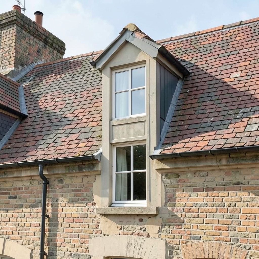
A dormer window — a structure projecting from the main roof slope, containing a window in a vertical face and its own small roof above it — is the most common architectural intervention for adding natural light and ventilation to a habitable roof space, and its design quality is the detail that most directly determines whether the habitable loft feels like a designed room or like a converted storage space that was granted windows as a minimum concession to occupancy. The dormer is not a functional addition to a finished roof. On a well-designed building, the dormer is part of the roof’s original architectural conception, positioned and proportioned as deliberately as any other window in the building.
The dormer roof form — the mini-roof that covers the dormer structure — is the design decision that most visibly communicates the dormer’s relationship with the main roof below it. A dormer with a pitched roof whose pitch matches the main roof’s pitch and whose ridge runs parallel to the main roof’s ridge reads as architecturally continuous with the building — a considered extension of the main roof’s geometry rather than an applied addition. A flat-roofed dormer on a pitched main roof reads as a functional addition made for maximum internal headroom rather than for architectural coherence, and on a period building that reading undermines the building’s character in a way that the flat dormer’s internal space efficiency cannot compensate for.
The dormer width relative to the bay spacing of the building below it is the proportional constraint that most dormer designs violate in the pursuit of maximum internal area. A dormer whose width exceeds the structural bay of the wall below it reads as oversized for the building — a heavy addition that the facade’s compositional logic cannot accommodate without visual disruption. A dormer sized within the bay width, centered on the window below it in the wall, reads as belonging to the building’s proportional system, and that belonging is what makes the dormer an architectural asset rather than an extraction of internal volume at the cost of external character.
39. A Velux and Roof Light Design
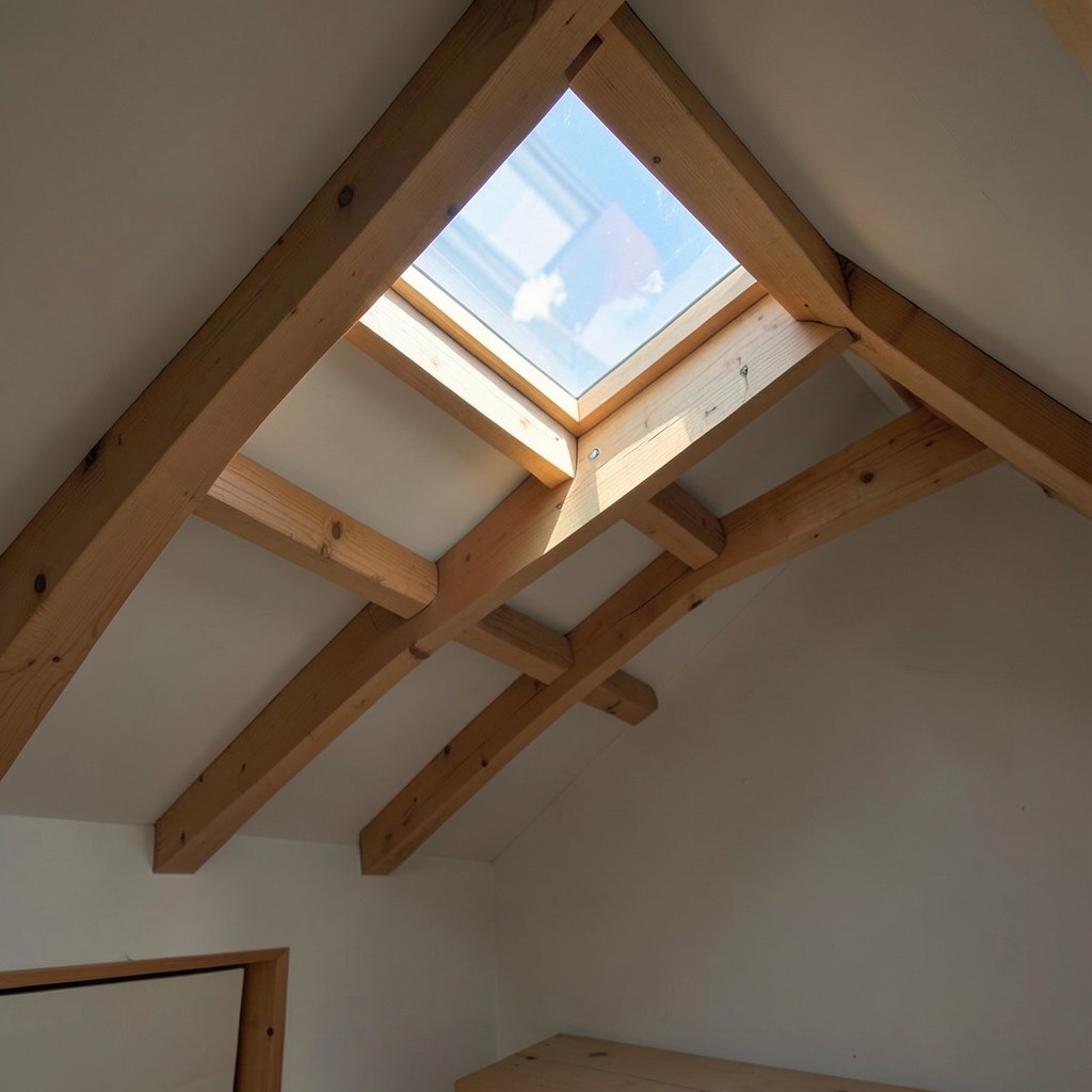
A roof light — a glazed opening in the roof plane, flush with the roof surface or projecting minimally above it, providing natural light and ventilation to the room below through the roof rather than through a wall window — changes the internal atmosphere of the room it serves more dramatically than any equivalent window area in a wall surface, because overhead light has a quality and a distribution character that no lateral light source replicates. The room lit by a roof light has a quality of being inside a lantern — the light falls from above onto the horizontal surfaces, the walls receive reflected light rather than direct light, and the room’s overall luminance is higher and more even than the equivalent window area in a vertical surface provides.
The specification of a roof light requires careful attention to the solar gain management that all roof-level glazing demands, with the additional consideration that a roof light’s solar collection area per unit of glazed aperture exceeds that of a vertical window of the same dimensions because the roof slope presents the glazing at a closer angle to the sun’s path than a vertical wall surface does. A roof light on a south-facing slope without solar control glazing or an external blind admits direct sunlight to the room below for the full duration of the sun’s movement across the roof, which produces the summer overheating that the room’s occupants manage by drawing the internal blind — reducing the daylighting benefit to the level of a diffused glow rather than the clear overhead daylight that is the roof light’s primary contribution.
The structural opening in the roof for a roof light requires the rafter or purlin arrangement at the opening’s position to be modified in the same way as a dormer opening: doubled trimmer rafters at each side, a header rafter spanning between them at the top of the opening, and the trimmer-to-header junction at the structural connection standard that transfers the interrupted rafter’s load around the opening. The structural work for a single roof light opening in standard rafter construction is straightforward carpentry; the structural work for a large roof light spanning multiple rafter bays requires the structural engineer’s involvement to design the header beam and its bearing support.
40. A Colorbond Steel Roof Design
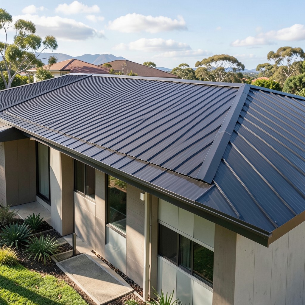
Colorbond steel — the pre-painted steel roofing product developed in Australia and now specified internationally for its combination of light weight, weather resistance, color stability, and the manufacturing consistency that a factory-produced steel product provides across large roof areas — is the roof covering that dominates the residential and commercial building market in Australia and that has gained a significant international following as contemporary residential architecture has moved toward the metal roof aesthetic that Colorbond’s flat pan and corrugated profiles deliver at a cost point below standing seam zinc or copper.
The color range of the Colorbond system — a curated palette of muted, natural tones whose selection reflects the specific color relationships of the Australian landscape — provides the design tool that the system’s specification allows: a roof color choice made in relationship to the building’s cladding and the surrounding landscape rather than constrained to the grey, black, or terracotta of the conventional tile market. The darker tones in the Colorbond range — Ironstone, Monument, Woodland Grey — produce the specific quality of a roof that recedes into the building’s profile rather than reading as a separate element, which suits the contemporary residential aesthetic that wants the building’s massing to read as unified rather than as wall plus roof.
The thermal performance of a Colorbond steel roof in high solar gain conditions — the Australian summer, the Mediterranean climate, or any high-altitude site with intense solar radiation — is addressed through the specification of the Thermatech solar reflectance technology incorporated into the darker Colorbond palette, which reflects a greater proportion of the sun’s infrared radiation than a standard painted steel surface absorbs. The reduction in solar heat gain through a reflective steel roof in summer reduces the cooling load on the building below and is the thermal performance specification that the building’s energy modelling should confirm before the roof color is fixed.
41. A Roof Terrace Design
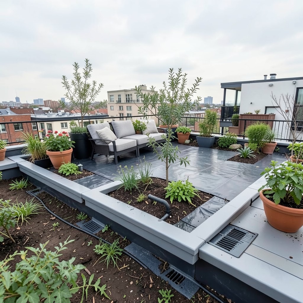
A roof terrace — a designed outdoor living space on a flat or low-pitch roof, surfaced for occupation, furnished, and planted as an outdoor room at roof level — is the urban residential design ambition that converts the building’s largest unused horizontal surface into genuinely productive domestic space, and it is the feature whose engineering, waterproofing, and structural requirements are most consistently underestimated by homeowners who encounter the concept in a magazine and instruct a contractor without the specialist roof terrace design input that the project genuinely requires.
The waterproofing of a roof terrace substrate — the membrane that prevents water from the occupied surface from entering the roof structure and the building below — must be specified at a higher performance standard than a standard flat roof membrane, because the roof terrace introduces the additional loading, the foot traffic, and the point loads of furniture and planting that a standard roof membrane was not designed to accommodate without damage. A root-resistant, traffic-rated waterproofing system — either a liquid-applied polyurethane system, a reinforced bituminous membrane, or a high-performance single-ply product with a protective overburden layer — provides the performance envelope that roof terrace use requires and that a standard flat roof specification does not.
The drainage design of a roof terrace must account for the additional water retention of the planting substrate, the reduced surface fall that the deck or paving layer may introduce, and the blocking risk that plant debris, soil wash, and general occupancy deposits create at the drainage outlets. A roof terrace drainage system requires more outlets per unit of roof area than a standard unoccupied flat roof, and each outlet must be accessible for inspection and cleaning without removing the deck or paving surface — the access provision that most roof terrace installations overlook and that produces the blocked drain emergency that the building’s occupants discover during the first heavy rainfall after installation.
42. A Copper Flashing Roof Detail
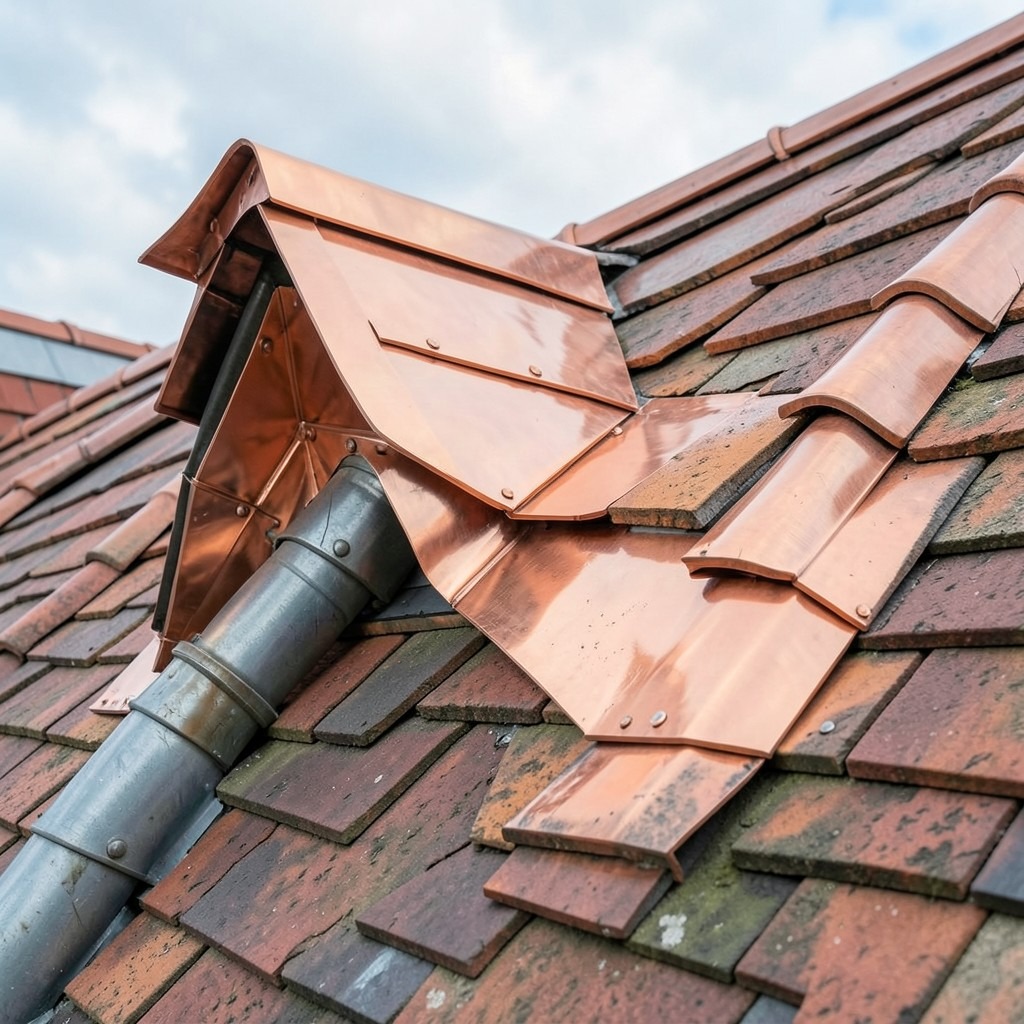
Copper flashings — the sheet copper details at the roof’s vulnerable junctions, including the abutment between the roof and a parapet wall, the soakers beneath tile courses at a hip or valley, the stepped flashing at a chimney stack, and the apron at a dormer front — are the specific roof details whose material quality most directly determines the roof’s long-term weather resistance at the junctions that pitched and flat roof surfaces alone cannot seal. The flashing is not the roof. It is the component that makes the roof’s joints work, and a roof with excellent tile or membrane coverage and poor flashings is a leaking roof waiting for the first wind-driven rain event to reveal it.
Copper as the material for roof flashings provides the combination of workability, durability, and self-sealing patina formation that makes it the reference standard against which all flashing materials are measured. The soft-temper copper that roofers cut, fold, and dress to the complex profiles of chimney flashings and dormer aprons without the cracking that harder metals exhibit at tight bends, and the corrosion-resistant patina that develops on the exposed copper surface within the first years of installation, are the specific material properties that justify copper’s premium over the lead that it replaces in building regulations that restrict lead use for environmental reasons.
The junction between a copper flashing and a dissimilar metal roof structure — a zinc standing seam roof, a steel gutter, or an aluminium fascia — requires the isolation of the copper from the dissimilar metal to prevent the galvanic corrosion that the electrochemical potential difference between copper and most other metals drives at their contact point in the presence of water. A physical separator — a bituminous tape, a rubber gasket, or a non-metallic isolation strip — at every copper-to-dissimilar-metal contact prevents the galvanic corrosion that an ignorant or careless installation allows to develop silently over years before the corrosion damage becomes visible.
43. A Traditional English Clay Plain Tile Roof
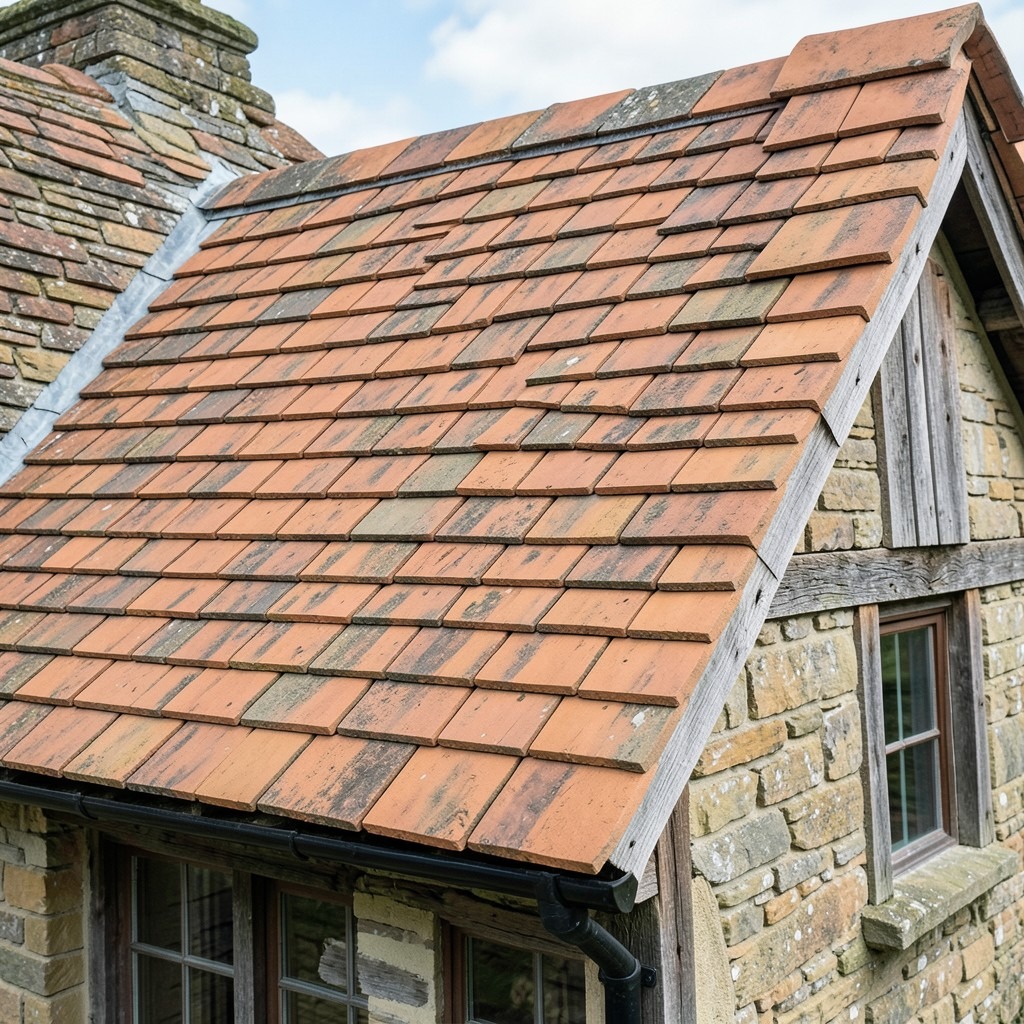
The English clay plain tile is the roof covering that most directly expresses the character of the English domestic vernacular building tradition — a small-format, double-lapped clay tile in the warm red-brown tones of local clay, laid in staggered courses on a close-boarded or counterbattened roof structure, with the slight surface camber of the handmade tile producing the gentle undulation of a roof surface that the machine-made flat tile does not replicate at any production specification. The plain tile roof on a Kent farmhouse, a Surrey cottage, or a Sussex oast house is not a historical reference — it is the material belonging of a building to the landscape that produced both the building and the clay that covers it.
The gauge of a plain tile roof — the exposed face of each tile course, which determines the number of courses per unit of roof height and the visual scale of the tile pattern on the roof surface — is calculated from the tile’s length, the minimum head lap requirement for the roof’s pitch and exposure, and the tile’s fixing nail hole position. A standard plain clay tile of two hundred and sixty-five millimeters length at a thirty-five-degree pitch in a moderate exposure zone requires a head lap of sixty-five millimeters, producing a gauge of one hundred millimeters — ten courses per meter of rafter length. The visual density of this course frequency is the plain tile roof’s characteristic texture, and it is this density that produces the fine-grained richness that no large-format tile approximates at equivalent viewing distance.
The bonnet hip tile — the purpose-made plain tile format that caps the hip junction of a plain tile roof, curving over the hip ridge in a continuous capping that matches the scale and character of the plain tile below it — is the detail that completes a traditional English plain tile roof at its most exposed junction. The alternative hip treatments of a half-round or angular ridge tile read as inconsistent with the plain tile’s fine scale, and the lead-soaker hip without any capping tile reads as a maintenance specification rather than as the designed detail that the plain tile roof’s character and the building’s architectural quality demand.
44. A Living Roof on a House Extension
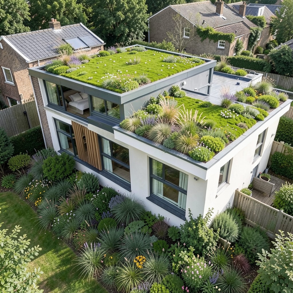
A living roof on a single-storey house extension — the planted green roof covering applied to the extension’s flat or low-pitched roof, visible from the house’s upper-floor windows and from the garden as a planted surface rather than a hard roof plane — is the domestic building application that most closely integrates the planted roof aesthetic into the daily experience of the household, because the view from above onto the planted roof surface makes the extension’s roof a designed garden element rather than a hidden building component. The living roof on an extension is the feature that the bedroom window looks out onto, and that changes the design requirements from structural performance to visual experience.
The species selection for a living roof on a house extension that is viewed primarily from above — from an upper-floor window or from a raised garden level — prioritises the visual character of the planted surface rather than its ecological performance alone. A sedum carpet provides the reliable extensive roof performance but reads from above as a green mat with seasonal flower dots rather than as a designed planting with the compositional quality that a roof viewed as a garden surface deserves. A designed planting scheme — low ornamental grasses interspersed with sedum and wildflowers, arranged in flowing drifts that read as a designed composition from the overhead viewing position — elevates the living roof from a green engineering solution to a designed garden element.
The relationship between the living roof’s planted surface and the garden below — the visual connection between the roof’s planted plane and the planted ground level, either through species repetition that creates continuity between the roof planting and the garden planting, or through a deliberate contrast that makes the roof’s planted surface read as a separate designed element — is the landscape design decision that determines whether the living roof feels integrated into the property’s overall outdoor design or reads as an isolated planted surface with no relationship to the garden it sits above.
45. A Roof With Integrated Gutters and Hidden Drainage
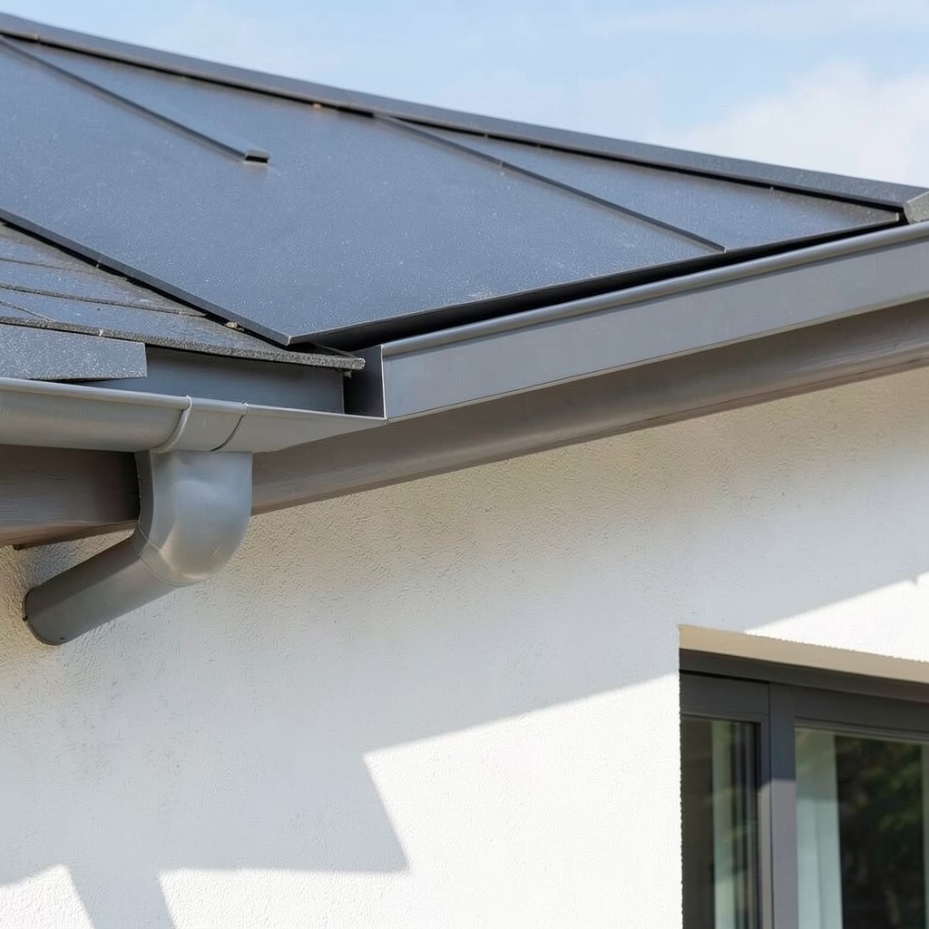
A roof with integrated gutters — box gutters formed within the roof structure rather than hung from the fascia as external elements, concealing the drainage infrastructure within the building envelope — is the roof design solution that produces the clean, uninterrupted eave profile that contemporary and minimalist architectural directions require and that the external half-round or ogee gutter, however well-maintained, cannot provide at the eave detail quality these design directions demand. The integrated gutter is the detail that makes the roof’s edge look resolved rather than equipped.
The box gutter — the internal gutter formed at the eave by a lined channel within the roof structure, typically between the outer face of the wall and the first rafter, with the drainage outlet through the wall to an internal or external downpipe — requires the gutter’s lining to be a fully waterproof material continuous with the roof’s waterproof layer above it, because any breach in the liner allows water to enter the roof structure from the point of highest water concentration in the entire roof’s drainage system. The box gutter’s liner — in lead, zinc, GRP, or a liquid-applied waterproofing membrane — must be installed without laps in the direction of water flow, must be provided with the expansion accommodation that thermal cycling requires, and must be accessible for inspection without removing the roof covering above it.
The overflow provision for an integrated box gutter is the design element that most roof drainage designs omit and that most building surveyors identify as a deficiency in their assessment of roof drainage systems. A blocked box gutter outlet with no overflow provision fills to the level of the adjacent roof structure and eventually overflows into the building through the lowest available path — typically the internal wall junction at the gutter’s end. An overflow outlet positioned fifty to seventy-five millimeters above the gutter’s normal drainage outlet level discharges overflow water to the building’s exterior rather than to its interior, and its position — visible on the building’s external face — also serves as the diagnostic indicator that the primary outlet requires clearing.
46. A Roof With Skylights for Natural Light
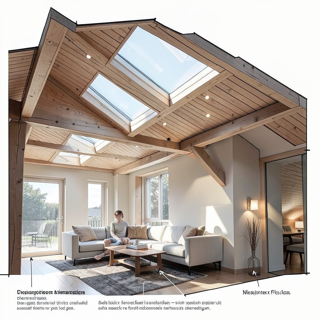
A roof designed from the beginning to accommodate multiple skylights — not as retrofit additions inserted into an existing roof covering but as designed openings positioned and sized in relationship to the spaces below them and to the roof’s overall structural and weather envelope — provides the building with the daylighting quality that transforms single-storey or low-ceiling interior spaces from adequate to genuinely atmospheric. The deliberate skylight roof is the design decision that says the building’s interior quality matters as much as its exterior appearance, and that the roof’s function extends beyond weather exclusion to include the active management of natural light within the building.
The positioning of skylights within a roof design must be resolved in section — understanding where the light from each opening falls at different times of the day and at different seasons — before the positions are fixed in plan. A skylight positioned directly above the primary seating area in a living room admits the overhead light that illuminates faces from above, which is theatrically dramatic but physiologically uncomfortable for sustained occupation. The same skylight positioned to one side of the seating area, illuminating the adjacent wall and reflecting light toward the seating from the wall surface, provides the quality of indirect natural light that is comfortable for extended occupation without the direct overhead intensity that the centered position produces.
The glazing specification for multiple skylights in a single roof must address the aggregate solar gain contribution of the combined opening area, because the solar gain through multiple skylights accumulates as a total heat load that the single skylight’s contribution does not represent. Three skylights of one square meter each contribute three square meters of solar collection area to the building’s summer heat gain, and the glazing specification — the solar heat gain coefficient, the g-value of the glazed unit — must be selected for the combined contribution rather than for each skylight individually.
47. A Slate Roof With Ornamental Ridge Details
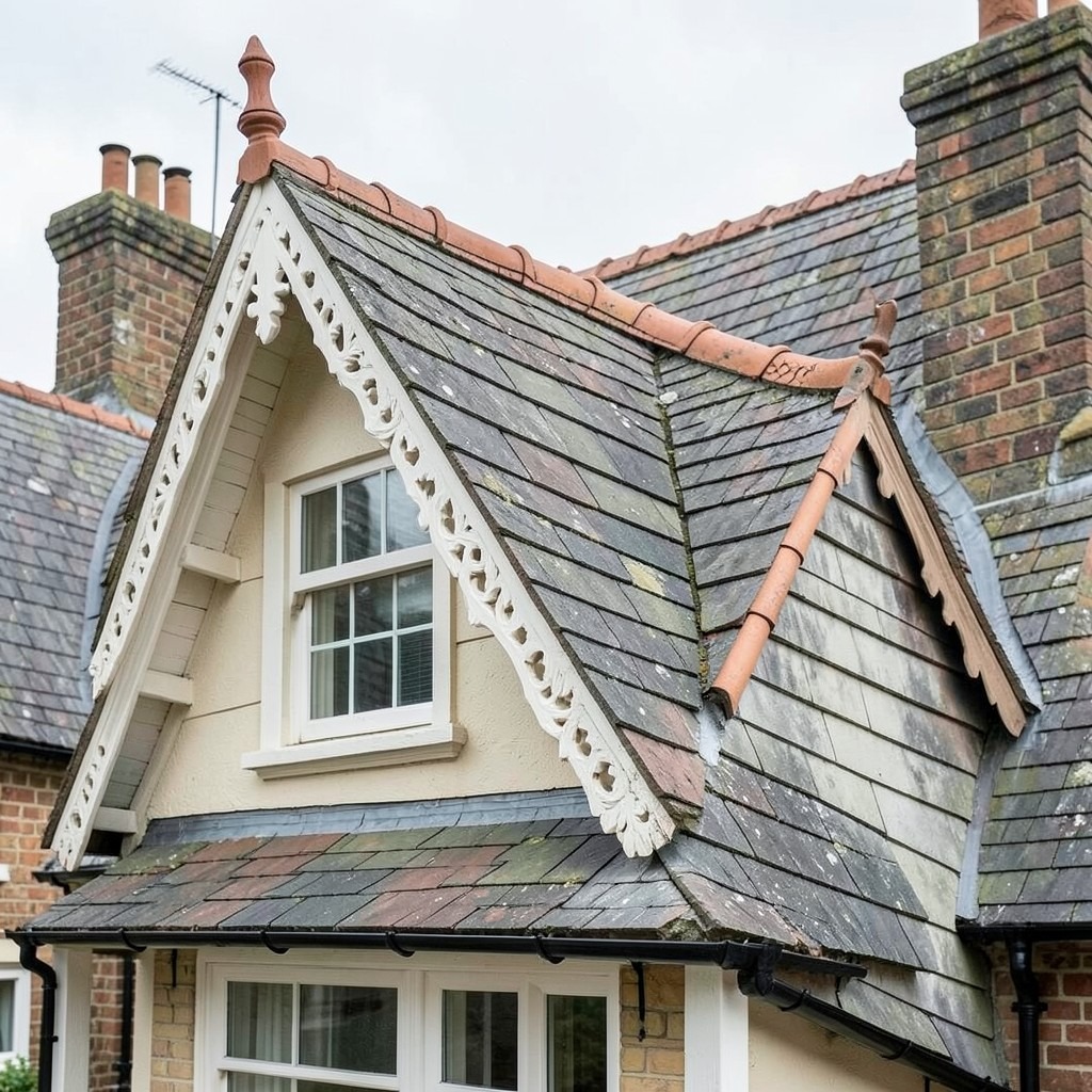
A natural slate roof with ornamental ridge details — purpose-made decorative ridge tiles, finials, and hip ornaments in terracotta or cast iron that cap the ridge and hip junctions with the architectural embellishment of the Victorian and Edwardian roofing tradition — is the roof specification that most directly connects a building’s roof to the decorative ambitions of the domestic architecture period whose character the building expresses. The ornamental ridge is not a modern indulgence. It is the historically accurate completion of a roofing tradition that understood the ridge as the building’s most elevated architectural element and treated it accordingly.
The scalloped or crested clay ridge tile — available from the specialist manufacturers who continue to produce the Victorian profile ranges for the heritage market — provides the decorative profile at the ridge that the plain half-round ridge tile’s simplicity does not attempt. The crest height above the ridge boarding, the profile of the scalloped edge, and the dimensions of the tile all derive from the specific historical period of the building’s construction, and the specification of period-correct ridge tiles for a Victorian or Edwardian property is the roofing detail that most visibly communicates the building’s restoration quality to the informed observer.
The finial — a decorative terminal element at the ridge end, at the hip apex, or at the intersection of ridge and hip — is the ornamental detail whose contribution to the roof’s character is disproportionate to its physical scale. A terracotta finial at the gable apex of a Victorian cottage, or a cast iron hip finial at the corner of an Edwardian villa, completes the roof’s decorative program with a punctuation mark that reads from the street as a sign of the building’s design completeness. The absence of finials from a period building that was designed to carry them is a design subtraction as visible as any other missing architectural element.
48. A Patinated Steel Corten Roof Design
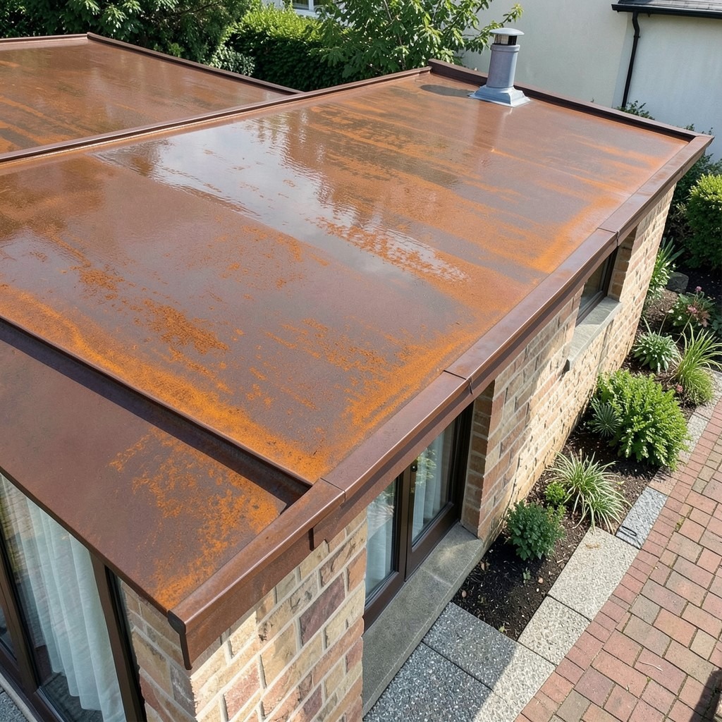
Corten steel — the weathering steel alloy that develops a stable rust patina on its surface when exposed to the atmosphere, forming the dark orange-brown protective layer that is simultaneously the material’s corrosion resistance mechanism and its most distinctive visual quality — is the roof material that most directly challenges the conventional association between rust and deterioration. On Corten, the rust is the protection. The oxidised surface layer that forms in the first two to three years of outdoor exposure is not a sign of corrosion progressing through the metal — it is the stable patina that stops further corrosion by sealing the surface against the moisture and oxygen that drive the corrosion process in unalloyed steel.
The patina development of a Corten steel roof is the visual performance that distinguishes the material from all other metal roof options: the surface passes through a sequence of tones — from the initial bright metallic grey of new steel through the orange rust of early oxidation through the progressive darkening toward the deep, rich, dark brown of fully stabilised Corten patina — that produces a different roof color at every stage of the patination process and reaches the final stable tone after three to five years of outdoor exposure. The building that receives a Corten roof is living with a slowly changing material performance rather than a fixed finished product, and that temporal quality is part of what makes Corten a design material rather than simply a construction material.
The run-off from a Corten roof surface during the active patination phase — the period when the patina is still developing and the orange iron oxide is mobile on the surface in wet conditions — stains any porous material it contacts: the paving below the eave, the masonry of the wall below the roof edge, and any garden planting that receives the run-off. The drainage from a Corten roof during patination must be directed away from surfaces that the iron oxide staining would damage aesthetically or structurally, and the adjacent paving should be in a non-porous material — granite, dense engineering brick — that the staining does not permanently mark.
49. A Rooftop Garden Room Design
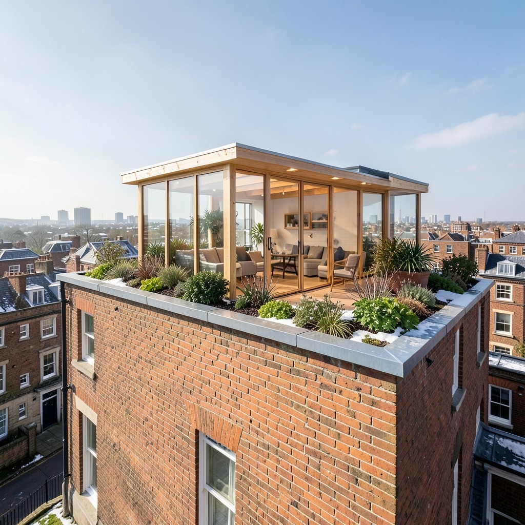
A rooftop garden room — a habitable structure built on the roof of an existing building, either as a lightweight glazed pavilion, a timber-framed room with planted surrounds, or a fully enclosed extension of the building’s upper floor onto the roof plane — is the architectural intervention that most dramatically changes a building’s relationship with its urban context and that provides the most compelling domestic experience available from a building’s highest level. The rooftop room occupies the position above the surrounding roofscape, connects the household to the sky and the city panorama that ground-level rooms cannot access, and converts the roof from the building’s weather-managed top surface into its most extraordinary inhabited space.
The planning consent requirements for a rooftop addition are the regulatory framework that most rooftop garden room projects must navigate before structural or material considerations become relevant, and the planning sensitivity of roof additions in urban conservation areas, listed buildings, and Article 4 Direction areas is the constraint that determines whether the project is possible in its intended form or must be modified to achieve consent. A lightweight, set-back rooftop addition — positioned behind the parapet line so that it is not visible from the street — is the planning approach that most frequently achieves consent for rooftop additions in sensitive urban contexts, because its visual impact from the public realm is minimal.
The structural implication of a rooftop addition is the loading it adds to the existing building’s structure at the point where the existing structure has the least spare capacity — the top of the wall and the existing roof structure. The weight of a rooftop garden room, its occupants, its furniture, and the snow and wind loads that the elevated position makes more severe than at ground level, must be transferred through the existing building’s structural system to the foundations. A structural engineer must assess the existing building’s structural capacity for the proposed loading and specify the strengthening that the additional load requires before any design for the rooftop structure proceeds.
50. A Roof Design That Works for the Building It Covers
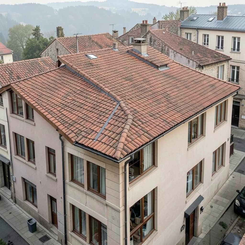
The roof design that works is not the one that was most admired on another building in a different context, at a different scale, in a different climate, or for a different architectural purpose. It is the one whose form, material, pitch, detail, and drainage were all decided in relationship to the specific building it covers — its plan, its wall height, its architectural character, its structural system, its exposure condition, and the household’s honest assessment of the maintenance commitment they are prepared to make across the roof’s service life.
Start with the form. The building’s plan, its internal volume requirements, its relationship with the adjacent buildings and the street, and the planning framework that governs its appearance determine the roof form options available before any material is considered. Within those options, the form that most honestly expresses the building’s architectural character and that produces the internal volume the building needs is the right starting point — not the form that was seen in a magazine last month or that the contractor has the most experience installing quickly.
Choose the material for the long term rather than the installation. The roof material decision compounds over the building’s life in a way that almost no other building specification decision does — the cheap material chosen for initial cost savings produces either a lifetime of maintenance costs or an early replacement cost that the premium material would have deferred by decades. The roof that was worth doing is always the one that was worth doing properly from the first tile laid at the eave to the last ridge cap mortared at the apex, and the building it covers carries that quality visibly in every year of its standing life. Design the roof that the building deserves, and the building will tell you it was right.
Leave a Reply